
About the book
The Path for a great Binnary
About the book:
The Path for a Great Binary is a bridge between history, logic, and the raw machinery that powers modern computation. It begins where most books end - at the bit, the pulse of 0 and 1 - and walks backward through the origins of programming, assembly, and the abstract logic that defined machines before electricity.
Through the lens of reverse engineering, it connects Ada Lovelace’s vision and Babbage’s mechanical dreams with the binary language of today’s processors, offering readers not just technical knowledge, but philosophical context - a way to think like the machine, not merely program it.
This is not a programming tutorial. It is a mental excavation - a journey into how computation evolved, why binary won, and what it means to truly understand code at its most fundamental level.
About the author:
Leon is a cybersecurity strategist and reverse engineer with deep experience in malware analysis, system forensics, and low-level programming. Having worked in MSSP environments and trained analysts in incident response, he developed a framework that connects modern cyber defense to the origins of computing logic.
Beyond his technical expertise, Leon’s passion lies in education - helping new generations of analysts learn not only how systems work, but why they work that way. His approach blends historical insight, practical demonstration, and philosophical grounding - bridging the minds of Lovelace and Turing with the curiosity of today’s reverse engineers.
The Mission of The Path for a Great Binary
The Path for a Great Binary was written to bring some depth back into how we understand computers - to remind us that beneath all the layers of code, frameworks, and flashy tools, there’s a simple, beautiful logic that makes everything work. It’s about slowing down, peeling back the abstractions, and learning to see what really happens under the hood.
This book walks through those foundations - from the first sparks of logic and binary, to assembly, memory, and the way machines actually think. It’s made for anyone who wants to move past surface-level “how-to” tutorials and really learn how the silicon breathes - whether you’re diving into reverse engineering, malware analysis, or just curious about how computers tick.
The goal isn’t to make things sound complicated. It’s the opposite - to make the low-level world understandable, practical, and open to everyone.
That’s why the web version at greatbinary.win is completely free. It includes everything a beginner needs to start mastering computing from the ground up - no paywall, no missing pieces.
The paid version goes deeper, with more examples, exercises, and real-world applications for those who want to take it further - but the free version already gives you the full path to become fluent in how machines really work.
At the end of the day, The Path for a Great Binary is here to give everyone a way in - whether you’re opening a hex editor for the first time, or learning to read memory dumps like a second language.
Introduction
The Genesis of Binary: From Philosophy to Silicon
Before computers were made of metal and silicon, they were made of ideas.
Long before anyone soldered a circuit or wrote a single line of code, people were already trying to understand how logic worked - how to turn thought itself into something mechanical. They asked questions like: Can reason be measured? Can it be automated?
That curiosity became the seed of everything we now call computing. From philosophers debating logic to mathematicians defining structure and order, humanity was unknowingly laying the groundwork for binary the simple, almost poetic language of 1s and 0s that would later become the heartbeat of machines.
The Path for a Great Binary follows that transformation - from abstract philosophy to physical reality. It traces how ideas turned into hardware, how logic turned into electricity, and how human thought became encoded inside chips no wider than a fingernail. Every tool we use today - hexadecimal notation, memory stacks, logical gates, even high-level programming languages - started as a spark in someone’s mind. Nothing in computing was born perfect; it evolved through imagination, necessity, and countless failures. Understanding those roots isn’t just for historians - it’s a way to unlock power. When you know why things were built the way they are, you stop just using computers and start understanding them. You see the patterns beneath the surface, and that’s the first step toward mastering the machine.
This book connects three worlds: the history that started it all, the principles that make computers work, and the reverse engineering mindset that lets you take them apart and understand their logic. It begins with Ada Lovelace - the first to realize that a machine could do more than calculate - and Charles Babbage, who dreamed up the first programmable computer long before electricity entered the picture. Their ideas laid the intellectual foundation for everything that came after: conditional branches, loops, stored memory, and ultimately, binary logic.
Binary - the unshakable rhythm of 1 and 0, on and off - became the perfect bridge between human reason and machine precision. It wasn’t just efficient; it was pure. Two states. No confusion. No noise. Every color on your screen, every packet crossing the internet, every frame of every video you’ve ever watched - all of it collapses, at the deepest level, into that same binary pulse.
When you look at malware, assembly code, or the inner workings of a CPU, you’re not just studying software - you’re tracing the evolution of thought itself. The obfuscation, the logic, the flow - all of it descends directly from ideas that were once philosophical arguments about the nature of reasoning.
The Path for a Great Binary takes you through that evolution step by step - from Lovelace and Babbage’s mechanical visions to the silent electronic logic inside the modern CPU. You’ll learn how binary became the machine’s first true language, how assembly lets us communicate with it directly, and how those same principles can still be exploited, manipulated, or defended today.
By the end, you won’t just understand how computers work - you’ll understand why they work that way. You’ll be able to look at the code beneath the code, to see how every byte of data is really a reflection of human thought - structured, encoded, and made eternal in silicon.
Table of contents
About the book
The Path for a great Binnary
Before the Bit:
How Ada Lovelace Reverse Engineered the Future of Computing
1. Introduction: The Ghost in the Machine
2. The Mechanical Dream: Babbage's Analytical Engine
3. The First Programmer: Ada Lovelace's Vision
Ada Lovelace's Pioneering Vision in Computing
Controversy Surrounding Lovelace's Programming Claim
4. The Electronic Leap & The Binary Imperative
5. Conclusion: From Abstract Logic to Physical Reality
The Mechanical Dream: Babbage's Analytical Engine
From Binary to Characters: The ASCII Standard
From Machine Language to Human Sight
The Wall of Zeros and Ones: Why Binary Isn't Enough
Hexadecimal: The Analyst's Best Friend
ASCII: Giving Meaning to the Numbers
Conclusion: Two Lenses, One Truth
1. Hexadecimal to Binary Conversion
2. The 16 Hex - Binary Mappings
7. Visual Mapping (Hex Alphabet)
How the Processor Executes Instructions
The Building Blocks: Logical Gates
From Simple Gates to Complex Thought
The Bare Metal: A Practical Introduction to Assembly Language
Introduction: Speaking Directly to the Silicon
The Anatomy of an Assembly Program
The CPU's Workbench: Registers
The Program's Blueprint: Sections
Assembly Language Structure (General)
Example (x86 Linux Assembly - NASM Syntax)
A Practical Example (Windows): Speaking to the API
Deconstructing the Windows API Call
Conclusion: The Building Blocks of Execution
Deepdive - General Purpose Registers
FS – Thread-local / TEB Access (Windows x86)
GS – Not Utilized in 32-bit Windows, However, an Example is Provided
DS – Data Segment (Default for Most Data Access Operations):
ES – Extra Segment (Used with String Operations):
1.Key CPU Flags and Their Significance:
2. Bit Flags (Control/Option Flags)
1. Memory Allocation Type Flags
5. File & Section Mapping Flags
1. Introduction: Why the Stack Matters
Key Characteristics of the Stack:
3. The Stack in Function Calls
Function Call and Return Flow:
4. Reverse Engineering the Stack
Conclusion: The Stack as a Dynamic Blueprint
5. How the Stack Works: LIFO and Key Pointers
6. The Stack in Action: CALL and RET
CALL function_label: Invoking a Function
RET: Returning from a Function
Visualizing the Stack Frame: A Step-by-Step Example
Step 1: Pushing Arguments onto the Stack
Step 3: The Function Prologue - Setting Up the Frame
Step 4: Allocating Space for Local Variables
Weaponizing the Stack: The Buffer Overflow
Article 1
Code Before Computers

A History for Hackers and programmers
Before the Bit:
How Ada Lovelace Reverse Engineered the Future of Computing
0. Intro
This section explores the foundational concepts of Assembly (ASM) programming and malware operation, tracing their origins from early computational ideas to modern applications. We will emphasize that understanding the historical development of computation, from philosophical inquiries to mechanical and electro-mechanical machines, is crucial for comprehending the intricate relationship between hardware and software, and the sophisticated nature of contemporary malware. By exploring these historical roots, we can appreciate the elegance of low-level programming and how today's complex vulnerabilities are evolutions of early design principles.
1. Introduction: The Ghost in the Machine
To truly understand how modern programming in Assembly (ASM) and how malware operates at the silicon level, manipulating raw binary data and leveraging the deepest functions of an operating system, we must first embark on an archaeological dig. This isn't merely a history lesson, but an excavation into the abstract concepts that first gave machines a "ghost"-the ability to compute, to process information, and ultimately, to mimic thought.
Before the shimmering lights of a data center or the intricate logic of a microprocessor, there were profound ideas, visionary pioneers, and a compelling vision of a mechanical future that laid the groundwork for everything we call digital today. This journey takes us back to the foundational principles of computation, where logic gates were conceptualized, and the very notion of a program was a revolutionary thought. We'll explore how these early concepts, born from philosophical inquiries and mathematical breakthroughs, gradually transformed into tangible machines.
From the mechanical calculators of Pascal and Leibniz, through Babbage's Analytical Engine and Ada Lovelace's pioneering algorithms, to the electro-mechanical behemoths of the mid-20th century, each step was a crucial stride in defining the language and architecture of computation. Understanding these origins allows us to appreciate the elegance and efficiency inherent in low-level programming and the intricate dance between hardware and software. It reveals how the seemingly complex operations of today's malware are, in essence, highly sophisticated evolutions of these fundamental interactions, exploiting vulnerabilities that stem from the very design principles established in these early days.
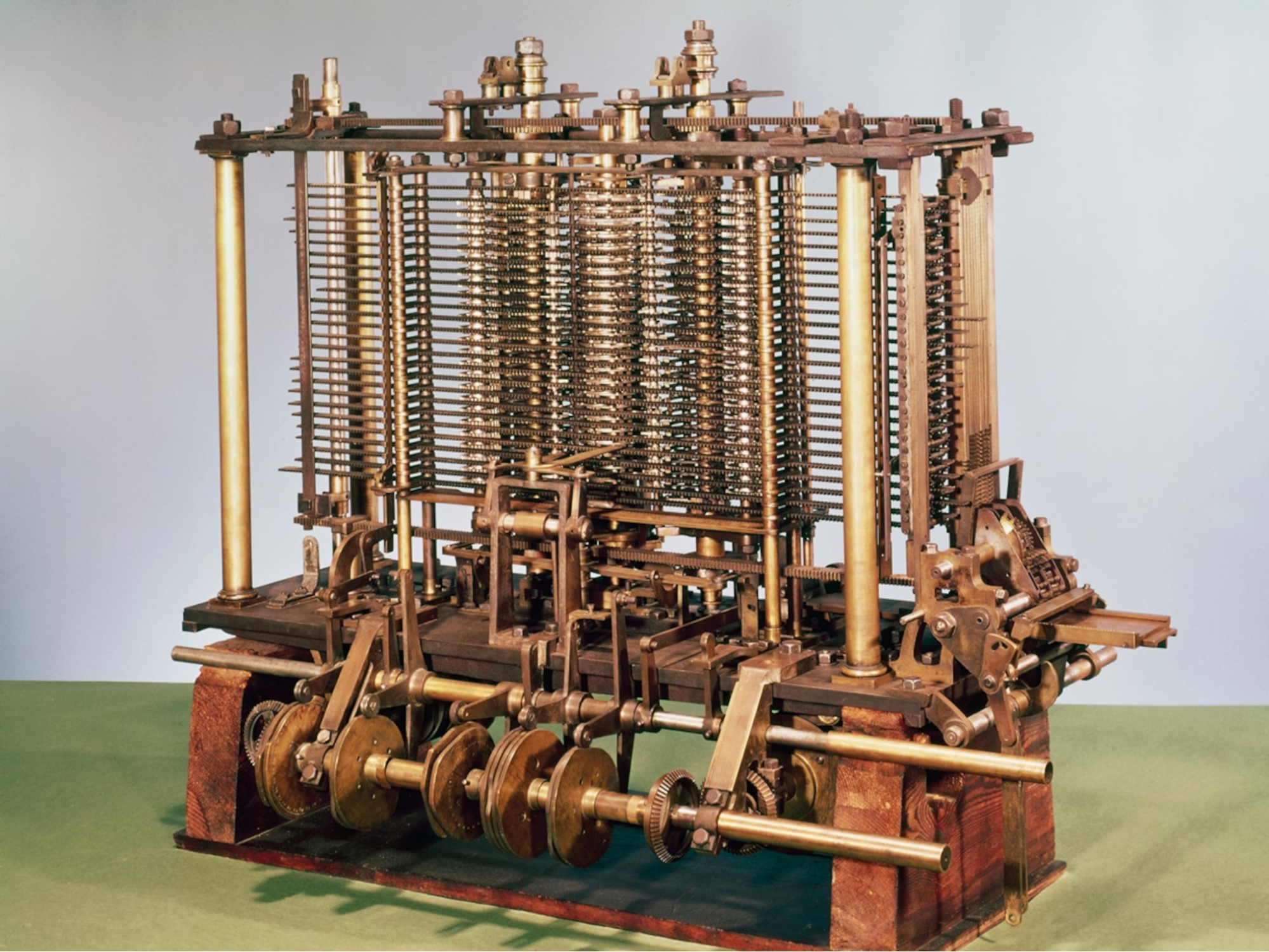
2. The Mechanical Dream: Babbage's Analytical Engine
In the years of computational history, Charles Babbage's Analytical Engine stands as a magnificent, theoretical beast of brass and iron-a marvel of Victorian engineering that, though never fully constructed, laid the conceptual cornerstone for modern computing. This purely mechanical, decimal-based machine, operating in base-10, was designed not merely to perform calculations, but to be programmable, a revolutionary idea for its era that ignited the spark of the digital age.
For reverse engineers, the Analytical Engine, with its gears, levers, and punch card instructions, was the first target system. To program it, one had to deeply understand its architecture and operational mechanisms. This process of comprehending its logic and devising operational sequences was the earliest form of systems analysis and low-level programming, requiring intimate knowledge to unlock its potential.
In the heart of every digital device lies a language of profound simplicity, a universal dialect spoken not in words, but in whispers of electricity-the binary system. The journey to this binary tongue began long before the electronic age, not with transistors or integrated circuits, but in the ambitious minds of pioneers like Ada Lovelace and Charles Babbage. Their work on the Analytical Engine, though never fully realized in their time, conceptualized the fundamental principles of computation: a programmable machine capable of executing sequences of instructions, storing data, and performing arithmetic operations. Lovelace, often credited as the world's first computer programmer, understood that the machine could do more than just crunch numbers; she envisioned its potential for manipulating symbols and creating complex algorithms, foreshadowing the very essence of modern software.
The elegance of binary, a system built on just two states-0 and 1, off and on, false and true-is its inherent simplicity and robust nature. This foundational language, while seemingly primitive, is the bedrock upon which all complex software and hardware are built.
Every click, every character typed, every image rendered, and every network packet transmitted, ultimately boils down to a meticulously orchestrated sequence of these binary bits. Understanding this fundamental layer is crucial for anyone seeking to delve into the intricacies of low-level programming, where direct manipulation of these bits and the underlying hardware allows for unparalleled control and, conversely, opens avenues for malicious exploitation.
It is at this level that the true "dialogue" between software and silicon occurs, a silent conversation that shapes the digital world around us, a world born from the dreams of Babbage and Lovelace.
From a reverse engineering (RE) perspective, the Analytical Engine can be seen as the original "black box" system. Charles Babbage designed its architecture, but for it to perform any function, its design needed to be analyzed. Then, a precise sequence of instructions had to be input using punch cards. This process fundamentally mirrors reverse engineering: understanding a system's internal logic to manipulate its behavior. |
3. The First Programmer: Ada Lovelace's Vision
Once upon a time, in the early 19th century, lived a remarkable woman named Ada Lovelace (1815-1852). She was the daughter of the famous poet Lord Byron, but it was her mother, Annabella Milbanke, who ensured Ada received an extraordinary education in mathematics and science-a truly rare opportunity for girls in those days! This special upbringing sparked a brilliant mind, and when Ada was just a teenager in 1833, she met a fascinating inventor named Charles Babbage and saw his incredible Analytical Engine. It was a mechanical marvel, designed to perform complex calculations, and it utterly captivated Ada.
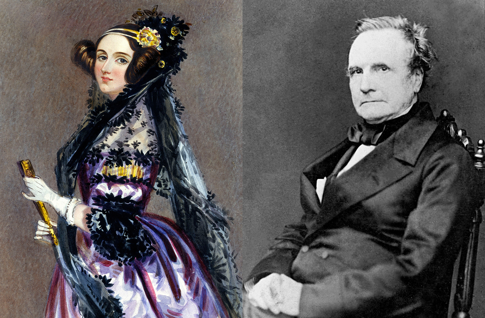
Ada Lovelace-left, Charles Babbage-right
A decade later, in 1843, Ada took Babbage's ideas and made history. She was translating an article about the Analytical Engine, and in her accompanying notes-which were much longer and more insightful than the original text-she published something truly groundbreaking. Within those notes was what many consider the world's very first computer program! It wasn't just a simple sum; it was a sophisticated, step-by-step plan, an algorithm, to calculate something called Bernoulli numbers. Imagine, a detailed set of instructions for a machine to follow, far beyond anything seen before!
But Ada's genius didn't stop there. While others saw the Analytical Engine as a giant calculator, Ada saw something more profound. She looked beyond its gears and levers and imagined its true potential. She famously pondered that the machine "might act upon other things besides number," suggesting it could manipulate symbols in all sorts of ways. She dreamed of a machine that could compose music or create beautiful graphics, not just crunch numbers.
This was a revolutionary idea: that a machine could be a creative partner, not just a tool for arithmetic. She understood, perhaps better than anyone else at the time, the abstract operations a machine could perform. Her vision laid the foundation for the entire field of computer science.
It’s worth noting, like many great pioneers, there’s been some discussion about her exact place in history. Charles Babbage did write some earlier programs, though they weren't published. However, Ada Lovelace's work stands out as the first published and most comprehensive explanation of a machine’s abstract power, clearly demonstrating a visionary understanding that continues to inspire us. She didn't just understand the machine; she saw its soul and its boundless future.
All together
Lovelace's profound foresight extended beyond mere arithmetic. She posited that the Analytical Engine could manipulate symbols beyond numerical values, foreseeing applications in domains such as music. This conceptualization marked a pivotal transition from calculation to computation, leading to her recognition as a "prophet of the computer age" for articulating the computer's potential beyond purely mathematical endeavors.
Babbage's "Analytical Engine" represented a magnificent, theoretical construct of brass and iron, designed to compute utilizing the familiar ten digits of the decimal system. However, Lovelace, in her renowned annotations, accurately predicted the machine's broader capabilities, delineating the very first algorithm and thereby establishing the foundational principles for modern software.
When computation ultimately transitioned from mechanical gears to the silent flicker of vacuum tubes and transistors, the ten-state decimal system proved excessively noisy and unreliable for the emerging electronic medium. The formidable challenge of accurately representing ten distinct voltage levels without error was immense. The solution, in stark contrast, was elegantly minimalist: instead of ten states, the machine would necessitate only two – the presence or absence of an electrical pulse. This "on" or "off," "one" or "zero" binary system perfectly harmonized with the physical nature of an electronic switch, thereby establishing an unambiguous and exceedingly rapid foundation upon which the entire digital world could be reliably constructed.
While the inaugural computers differed significantly from those in contemporary use, their underlying principles remain consistent.
Ada Lovelace's Pioneering Vision in Computing
While Charles Babbage is credited with conceiving the Analytical Engine, Ada Lovelace's contributions transcended mere translation and commentary. Her profound understanding enabled her to envision capabilities for the machine that even Babbage had not fully grasped. Stephen Wolfram highlights that Babbage's own unpublished algorithms lacked the sophistication and clarity of Lovelace's work, particularly her computation of the Bernoulli numbers. She actively drove the intellectual development of the machine's potential, rather than simply documenting it.
Wolfram further emphasizes Lovelace's unique ability to synthesize "a clear exposition of the abstract operation of the machine-something which Babbage never did" from his extensive correspondence. This demonstrates her exceptional talent for conceptualization, transforming the Analytical Engine from a mechanical invention into a powerful, abstract computational device. Her notes provided a fundamental framework for programming and utilizing such a machine for applications far beyond basic arithmetic, solidifying her status as a visionary in the nascent field of computer science.
Controversy Surrounding Lovelace's Programming Claim
Ada Lovelace is widely recognized as the first computer programmer due to her method, often cited as the world's first computer program. However, this claim is not without dispute. Critics such as Eugene Eric Kim and Betty Alexandra Toole challenge this designation. Charles Babbage, the Analytical Engine's inventor, asserted authorship of the algorithm in Note G and had developed earlier, largely unpublished programs between 1837 and 1840, preceding Lovelace's work. Dorothy K. Stein interprets Lovelace's notes as reflecting her mathematical uncertainty, Babbage's political motivations, and the social and cultural context of the era, rather than a definitive scientific blueprint.
Reverse Engineering Perspective: Ada Lovelace's insight offers a powerful lesson for reverse engineers: she envisioned capabilities beyond the machine's initial design. Babbage saw a calculator; Lovelace recognized a symbol manipulation engine with the potential for creating music or art. Similarly, when analyzing malware, you'll often encounter code that repurposes standard functions in unforeseen ways to achieve malicious ends. Grasping the abstract potential of a system is crucial. |
4. The Electronic Leap & The Binary Imperative
The shift from the intricate brass and iron of mechanical calculators to the silent, invisible flow of electrons within electronic circuits marked a monumental leap in computational history. While mechanical devices like Babbage's Analytical Engine could, in theory, operate on decimal principles, the advent of electronic computers brought forth a critical challenge: how to reliably represent and process numerical data using electricity.
The problem with directly translating the familiar ten distinct decimal digits (0-9) into electronic signals was profound. Each digit would ideally correspond to a unique, analog voltage level. However, maintaining ten precisely separated voltage levels in an electronic circuit proved to be incredibly noisy, unreliable, and prone to error. Fluctuations in power, interference, or even minor manufacturing inconsistencies could easily cause a "3" to be misinterpreted as a "2" or a "4." The system lacked the robust distinction necessary for accurate and consistent computation.
The elegant solution arrived in the form of the binary system. An electronic switch, the fundamental component of early computers (and modern ones, in transistor form), has only two inherently stable and unambiguous states: on (represented as 1) or off (represented as 0). This clear, dichotomous nature perfectly harmonized with the physical reality of electronics. With only two states, there was no ambiguity; a signal was either definitely "on" or definitely "off." This simple yet powerful concept provided a reliable, lightning-fast, and error-resistant foundation upon which all digital logic could be built. Every complex operation, every piece of data, could be broken down into these fundamental "yes" or "no" decisions, executed at speeds unimaginable by their mechanical predecessors.
5. Conclusion: From Abstract Logic to Physical Reality
The journey from the visionary concepts of early computing pioneers to the ubiquitous digital devices of today is a testament to the power of abstract logic finding its perfect physical manifestation. Ada Lovelace, with her profound insights into the Analytical Engine, glimpsed a future where machines could manipulate more than just numbers, envisioning the very essence of what we now call software. Her algorithms, conceived for a mechanical, decimal-based apparatus, were the first whispers of a machine's ability to "think" in structured, programmable sequences.
However, the leap from these mechanical dreams to a robust, scalable reality necessitated a fundamental shift in the machine's internal language. While Babbage's engine was a decimal marvel, the advent of electronics revealed the inherent unreliability of representing multiple states with fluctuating voltages. The elegant simplicity of the binary system-the unambiguous "on" or "off" of an electrical switch-provided the ideal foundation. It was in this two-state world that Lovelace's abstract logic for computation found its perfect, stable, and incredibly fast physical home. The complex operations she imagined for a decimal machine seamlessly translated into intricate patterns of 1s and 0s, giving birth to the digital age.
We've seen why computers speak binary. Now, we need to learn the language itself. In the next article, we'll explore how these simple 1s and 0s are grouped together to form the numbers, text, and instructions that are the building blocks of modern software.
The Mechanical Dream: Babbage's Analytical Engine
The application of decimal and hexadecimal systems to computers has a rich history driven by the need to bridge the gap between human understanding and machine operation.
Decimal's Early Role (and Challenges):
- Human Familiarity: From the very beginning of computing, humans naturally thought and worked in decimal (base-10). Charles Babbage's Analytical Engine, though mechanical, was designed to operate using decimal digits, reflecting this inherent human preference.
- Early Electronic Computers: The integration of human decimal and computer binary systems was a key design challenge in early computers. Binary-Coded Decimal (BCD) was a common method, encoding each decimal digit with a fixed number of binary bits (usually four) for easier input and interpretation by programmers.
- Drawbacks: However, directly processing decimal numbers within a binary machine was inefficient. Performing arithmetic operations on BCD numbers was more complex and slower than working directly with pure binary. This led to increased circuit complexity and slower processing speeds. As computers became more powerful and the need for speed grew, the reliance on purely decimal representations for internal processing diminished.
The Rise of Hexadecimal:
- Binary's Inherent Complexity: While computers operate most reliably using binary (1s and 0s), directly working with long strings of binary digits became incredibly difficult, time-consuming, and prone to error for programmers, especially as machine architectures grew more complex. A single byte (8 bits) is represented by eight 1s and 0s, and a 32-bit or 64-bit word becomes an unmanageable sequence of digits.
- Efficient Binary Representation: This is where hexadecimal (base-16) emerged as a powerful solution. Each hexadecimal digit can represent exactly four binary digits (bits). This means that a single hexadecimal digit can represent any value from 0 to 15, which perfectly maps to four bits (e.g., binary 1111 is hexadecimal F).
- Simplifying Machine Language: Hexadecimal significantly simplified the representation of binary data. Instead of writing long binary strings for memory addresses, machine instructions, or data values, programmers could use much shorter, more human-readable hexadecimal codes. For example, the binary 1011001011001111 becomes the much more manageable hexadecimal B2CF.
- Debugging and Memory Dumps: Hexadecimal is crucial for low-level programming, debugging, and memory analysis. Memory dumps and assembly language programming heavily utilize hexadecimal for opcodes, operand values, and memory addresses, allowing quick comprehension of machine state.
- Modern Relevance: Even with high-level programming languages, hexadecimal remains crucial for tasks like specifying colors (e.g., #FF0000 for red), representing MAC addresses, IP addresses (in some contexts), and working with bitmasks or flags in system programming.
In essence, while decimal provided the initial bridge to human understanding, its limitations in a purely binary environment led to the adoption of hexadecimal. Hexadecimal offered a much more efficient and human-friendly way to represent the underlying binary data, becoming an essential tool for anyone working at a lower level of computer architecture.
Binary-Coded Decimal (BCD): A primary method from the 1940s and 50s, heavily utilized in mainframe computers. Rather than converting an entire decimal number into a single long binary string, BCD represents each decimal digit with its own four-bit binary code.
For instance, the number 82 in BCD is:
1000 (for the 8)
0010 (for the 2)
Resulting in: 1000 0010.
This method was crucial for business and financial calculations as it eliminated rounding errors often associated with pure binary floating-point arithmetic.
Character Encoding (ASCII):
As computing evolved to be more text-based, the ASCII standard, finalized in the 1960s, became prevalent. ASCII assigns a unique binary code to every letter, symbol, and, importantly, to each decimal digit from 0 to 9. Today, when you press the '8' key, the computer receives the ASCII binary code for '8' (00111000).
From Binary to Characters: The ASCII Standard
The most fundamental of these systems is called ASCII (American Standard Code for Information Interchange). In this system, every character is assigned a specific 7-digit or 8-digit binary number. These groups of binary digits are called bits, and a group of eight bits is known as a byte.
Let's take the letter "A" as an example:
- The ASCII system assigns the uppercase letter "A" the decimal number 65.
- The computer then converts the decimal number 65 into an 8-bit binary sequence: 01000001.
So, when you type the letter "A", your keyboard sends the signal 01000001 to the computer's processor. The processor then tells the display to show the character associated with that binary code, which is "A".
This same principle applies to everything:
- The letter 'B' is decimal 66, which is binary 01000010.
- A lowercase 'a' is decimal 97, which is binary 01100001.
- The number '9' (as a character) is decimal 57, which is binary 00111001.
By stringing these bytes together, you can form any word or sentence. The phrase "Hi" would be represented in binary as the byte for 'H' followed by the byte for 'i': 01001000 01101001.
This concept extends to more complex data as well. Colors in an image are represented by binary codes for the amounts of red, green, and blue (RGB), and music is represented by encoding the frequency and amplitude of a sound wave into binary numbers thousands of times per second.
Article 2
The 0 and 1 make the world spin

Decoding Machine Language
0. Overview
From Machine Language to Human Sight
While we now understand that computers operate on the fundamental principle of binary-the eloquent dance of 0s and 1s-trying to interpret raw binary sequences directly is akin to attempting to read an entire novel composed of only two letters. It's a task that quickly becomes impossible for human comprehension, transforming meaningful data into an overwhelming, indecipherable stream.
This is precisely where Hexadecimal and ASCII emerge as indispensable translation layers, acting as the very "sight" that allows us to peer into and understand the machine's mind. Hexadecimal provides a compact and directly convertible representation of binary data, making long strings of 0s and 1s manageable and readable for low-level analysis. ASCII, on the other hand, bridges the gap between numerical binary values and human-readable characters, enabling the interpretation of text, symbols, and commands. Together, these two systems empower reverse engineers to translate the silent, binary whispers of a machine into a coherent narrative, revealing the true intent and function of its operations.
The Wall of Zeros and Ones: Why Binary Isn't Enough
While binary, the eloquent dance of 0s and 1s, is the perfect and most efficient language for computers, it presents an insurmountable wall of complexity for human comprehension. Trying to interpret raw binary sequences directly is akin to attempting to read an entire novel composed of only two letters. It's a task that quickly becomes impossible and incredibly error-prone, transforming meaningful data into an overwhelming, indecipherable stream.
Consider a single 32-bit value in its pure binary form:
11001111100010011010010101101110
Even for experienced professionals, quickly discerning patterns, values, or errors within such a long and undifferentiated string of 0s and 1s is exceedingly difficult and time-consuming. This inherent unwieldiness necessitates a more human-friendly approach-a system that remains compact enough for easy human interpretation yet maintains a direct and simple correspondence to the underlying binary structure, allowing for seamless translation.
Hexadecimal: The Analyst's Best Friend
Hexadecimal (base-16) is the solution for representing binary data in a human-readable format. It uses sixteen distinct symbols: the digits 0-9 and the letters A-F. Each of these symbols represents a value from zero to fifteen.
The Golden Rule
The most important concept to grasp is that one hexadecimal digit perfectly represents four binary bits (a "nibble"). This direct and consistent mapping is the fundamental reason hexadecimal is indispensable in computing, especially for low-level programming and analysis.
Table
Here is the essential lookup table for converting between hexadecimal, binary, and decimal:
Hex | Binary | Decimal |
0 | 0000 | 0 |
1 | 0001 | 1 |
2 | 0010 | 2 |
3 | 0011 | 3 |
4 | 0100 | 4 |
5 | 0101 | 5 |
6 | 0110 | 6 |
7 | 0111 | 7 |
8 | 1000 | 8 |
9 | 1001 | 9 |
A | 1010 | 10 |
B | 1011 | 11 |
C | 1100 | 12 |
D | 1101 | 13 |
E | 1110 | 14 |
F | 1111 | 15 |
Converting Hex → Binary:
To convert a hexadecimal number to binary, simply replace each hex digit with its 4-bit binary equivalent from the table above.
- F → 1111
- 2A → 0010 1010
- B7 → 1011 0111
- 1F2 → 0001 1111 0010
Converting Binary → Hex:
To convert a binary number to hexadecimal, group the binary digits into 4-bit chunks starting from the right. If the leftmost chunk has fewer than four bits, pad it with leading zeros. Then, translate each 4-bit chunk into its corresponding hex digit.
- 1111 → F
- 1010 0101 → A5
- 1100 1111 → CF
- 111001011011 → (pad left → 0001 1100 1011) → 1CB
Reverse Engineering Perspective: Hexadecimal is Your Native LanguageAs a reverse engineer, you will spend the vast majority of your time staring at a hex editor or the register/memory view within a debugger. Hexadecimal is, in many ways, the native language of these tools. Why? Because it perfectly aligns with the computer's underlying architecture. Two hex digits precisely make one byte (e.g., FF directly translates to 11111111 in binary). An 8-digit hex value immediately represents a 32-bit address or value, and 16 hex digits represent a 64-bit value. This incredibly clean and consistent mapping allows you to instantly visualize the raw binary data in a readable and manageable format. This is crucial for: - Spotting patterns in shellcode and malicious payloads.- Analyzing data structures in memory.- Discerning individual machine instructions and their operands.Without this fluency in hexadecimal, navigating the low-level world of a program's execution would be an almost impossible and error-prone task. |
ASCII: Giving Meaning to the Numbers
While hexadecimal provides a compact and human-readable way to represent raw binary data and numerical values, computers also need a method to represent text, symbols, and other characters that humans understand. This is where ASCII (American Standard Code for Information Interchange) becomes indispensable. ASCII is a character encoding standard that establishes a direct mapping between numerical values (which can be easily represented in binary or hexadecimal) and specific characters. It acts as the bridge that allows us to translate the machine's numerical language into meaningful words and symbols.
In the ASCII system, each character-whether it's a letter, a number, a punctuation mark, or a control character-is assigned a unique numerical value. This value can then be expressed in binary or hexadecimal, providing a consistent way for computers to store and process text.
For example, consider the uppercase letter 'A':
- In decimal, 'A' is represented by the number 65.
- In hexadecimal, this converts to 0x41.
- In binary, this is 01000001.
So, when a computer processes the binary sequence 01000001, it interprets it as the character 'A'.
This principle extends to forming words and sentences. When you type the word "Hi", the computer stores it as a sequence of bytes, where each byte corresponds to an ASCII character:
- 'H' is decimal 72, or binary 01001000.
- 'i' is decimal 105, or binary 01101001.
Therefore, the word "Hi" would be represented in binary as 01001000 01101001. This concatenation of individual character bytes forms the textual data that we interact with daily.
Reverse Engineering Perspective: ASCII as Your First Clue |
Conclusion: Two Lenses, One Truth
At the heart of every computer lies a singular, fundamental truth: binary data. This intricate dance of zeros and ones is the machine's native tongue, the bedrock upon which all operations are built. However, for humans to interact with and understand this profound digital reality, we require intermediaries-translators that bridge the vast chasm between raw electrical signals and meaningful information. This is where hexadecimal and ASCII emerge as our two primary "lenses," each offering a distinct yet complementary perspective on the same underlying binary truth.
Hexadecimal, with its base-16 system, provides a remarkably concise and human-readable representation of the raw numerical values inherent in binary data. Every pair of hexadecimal digits elegantly encapsulates eight bits (a byte) of information, making large strings of binary much more manageable for the human eye and mind. This system perfectly aligns with the machine's architecture, allowing programmers and engineers to directly visualize and manipulate the machine code at a low level. It's the language of memory addresses, register contents, and the precise numerical values that drive the computer's internal logic. Through the hexadecimal lens, we glimpse the cold, hard facts of the machine's existence-the exact numerical state of its memory and processors.
Conversely, ASCII (American Standard Code for Information Interchange) provides the essential bridge for comprehending that same binary data as meaningful text, symbols, and commands. While the computer sees a sequence of numerical values, the ASCII standard dictates how those values correspond to letters, numbers, punctuation marks, and control characters that we, as users, understand. It's the mechanism that transforms a binary sequence like 01000001 (which is 41 in hexadecimal) into the capital letter 'A' on our screens. This lens allows us to interact with computers in a language familiar to us, enabling everything from word processing to web browsing. Without ASCII, the binary stream would remain an inscrutable numerical deluge, devoid of the communicative power we take for granted.
Together, these two seemingly disparate systems empower us to translate the silent, binary language of the computer into a coherent and understandable narrative. Hexadecimal provides the precise, numerical detail, revealing the fundamental building blocks of digital information. ASCII imbues those blocks with human-centric meaning, transforming numerical patterns into the words and symbols that shape our digital experience. By mastering both lenses, we gain a comprehensive understanding of how a computer truly stores and represents information, bridging the gap between its purely electrical existence and our human need for interpretation and interaction.
Now that you can read the data a computer is storing, understanding its foundational language through the powerful dual perspective of hexadecimal and ASCII, it's time to understand the machine that actually processes that data. Having explored how information is represented, we are now poised to delve into the very heart of the computer's operations. In the next chapter, we'll open up the black box and look at the brain of the machine: the Central Processing Unit (CPU) and its fundamental building blocks, the logic gates, which are responsible for manipulating these very binary truths.
1. Hexadecimal to Binary Conversion
0. Overview
Computers fundamentally process information in binary (base-2), utilizing sequences of 0s and 1s to represent all memory values. However, these binary strings quickly become difficult for humans to read.
For example, a 32-bit (4-byte) binary sequence like:
11111111 00000000 10101010 11001100
is already challenging to interpret, even for experienced individuals, making debugging and analysis prone to errors.
To overcome this, Hexadecimal (base-16) was adopted. It offers a compact, human-friendly representation of binary while maintaining a direct relationship with the underlying binary structure. Its key characteristics are:
- Expanded Character Set: Hexadecimal uses digits 0–9 and letters A–F to represent values from 0 to 15, allowing each digit to convey more information than a single decimal digit.
- Direct Correspondence to Binary "Nibbles": Each hexadecimal digit directly corresponds to four binary bits (a "nibble"). This is its most crucial feature.
- Simplified Conversion: This direct correspondence eliminates the need for complex arithmetic during conversion between hex and binary, greatly reducing the potential for errors.
The advantage of hexadecimal over decimal (base-10) in representing binary data is clear:
- Decimal's Inconsistency: Decimal does not align consistently with binary. A single decimal digit can require 3 or 4 bits, but not a fixed amount, making direct mapping less intuitive.
- Hexadecimal's Clean Mapping: Hexadecimal provides a perfectly clean and even mapping:
- 1 hex digit = 4 bits
- 2 hex digits = 1 byte (8 bits)
- 8 hex digits = 32 bits
- 16 hex digits = 64 bits
Essentially, hexadecimal acts as a bridge between the machine's binary world and human understanding. It significantly enhances productivity and reduces cognitive load for anyone working with low-level computer data by making binary information much more readable, writable, and manipulable.
1. The Core Rule
The fundamental principle is that
one hexadecimal digit precisely equals four binary bits (a nibble).
This direct mapping is why hexadecimal is essential in areas like assembly language, debugging, and memory inspection.Hexadecimal (hex) is vital in computer science and low-level programming because one hex digit precisely equals four binary bits (a nibble). This direct mapping simplifies interpreting binary code.
This mapping offers:
- Conciseness and Readability: Hex drastically shortens long binary numbers (e.g., 8-bit 11110000 is F0 in hex), making data easier to read and understand.
- Direct Translation: Each hex digit (0-9, A-F) uniquely represents a four-bit binary sequence, allowing straightforward conversion without complex calculations.
Hex is indispensable in:
- Assembly Language: Concisely represents machine code, memory addresses, and register values.
- Debugging: Provides a human-readable view of binary data for identifying patterns and errors.
- Memory Inspection: Hex editors and debuggers display memory contents in hex for analyzing data structures.
- Color Codes: Represents colors in web development (e.g., #FF0000).
- MAC Addresses: Formats unique network interface identifiers (e.g., 00:1A:2B:3C:4D:5E).
In essence, hex bridges binary and human readability, streamlining low-level data tasks.
2. The 16 Hex - Binary Mappings
Memorize this table.
It is the alphabet of low-level computing.
Hex : Binary : Decimal
0 : 0000 : 0
1 : 0001 : 1
2 : 0010 : 2
3 : 0011 : 3
4 : 0100 : 4
5 : 0101 : 5
6 : 0110 : 6
7 : 0111 : 7
8 : 1000 : 8
9 : 1001 : 9
A : 1010 : 10
B : 1011 : 11
C : 1100 : 12
D : 1101 : 13
E : 1110 : 14
F : 1111 : 15
3. Converting Hex → Binary
Rule: Replace each hex digit with its 4-bit equivalent.
Examples:
F → 1111
2A → 0010 1010
B7 → 1011 0111
1F2 → 0001 1111 0010
4. Converting Binary → Hex
Rule: Group binary into 4-bit chunks (from right to left) and translate each chunk.
Examples:
1111 → F
1010 0101 → A5
1100 1111 → CF
1110 0101 1011 → (pad left → 0001 1100 1011) → 1CB
5. Why Hex is Used
- Compact: 1 hex digit replaces 4 binary digits.
- Precise: No wasted patterns (unlike BCD).
- Aligned: Cleanly maps to bytes, words, and larger registers.
- Readable: Easier for humans to parse than binary or long decimal.
6. Practice Examples
Hex F = Binary

Hex A5 = Binary

Hex FF = Binary

Binary 1101 0110 = Hex

Binary 1111 0001 1111 0010 =
Hex

7. Visual Mapping (Hex Alphabet)
Hex | Bin |
0 | 0000 |
1 | 0001 |
2 | 0010 |
3 | 0011 |
4 | 0100 |
5 | 0101 |
6 | 0110 |
7 | 0111 |
8 | 1000 |
9 | 1001 |
A | 1010 |
B | 1011 |
C | 1100 |
D | 1101 |
E | 1110 |
F | 1111 |
This is all you need on paper:
- The 16-value table,
- The chunking rule,
- A few examples.
After some repetition, you will read hex and binary as directly as reading the alphabet.
2. The Brain of the Machine
At the heart of every computer, smartphone, or digital device is a processor, more formally known as the Central Processing Unit (CPU). Think of the CPU as the brain of the computer; it's where the thinking happens. It takes in instructions from you, the software, and the hardware, and it performs trillions of calculations per second to make everything work. But how does a complex piece of silicon actually "think"? The secret lies in breaking down enormous tasks into incredibly simple, yes-or-no questions, which are handled by microscopic building blocks called logical gates.
How the Processor Executes Instructions
A processor's main job is to run a constant cycle of fetching, decoding, and executing instructions. To do this, it relies on three main components:
- The Control Unit (CU): This is the traffic cop or director of the CPU. It fetches instructions from the computer's memory and decodes them, turning software commands into signals that the rest of the processor can understand. It directs the flow of data, ensuring everything happens in the right order.
- The Arithmetic Logic Unit (ALU): This is the mathematical brain of the CPU. The ALU handles all calculations (addition, subtraction, multiplication, etc.) and all logical comparisons (such as determining if one number is greater than, less than, or equal to another). Every time you see a calculation on your screen, the ALU was responsible for it.
- Registers: These are small, extremely fast storage locations right on the CPU chip. They act as a temporary workbench for the ALU and CU, holding the specific pieces of data that are being worked on at that very moment.
These three parts work together in a continuous loop called the Fetch-Decode-Execute cycle, which is the fundamental process of all computing.
The Building Blocks: Logical Gates
So, how does the ALU actually perform a calculation? It's not with gears or beads, but by controlling the flow of electricity through millions of tiny electronic switches called transistors. These transistors are arranged into groups to form logical gates. A logical gate takes one or more binary inputs (an electrical signal that is either on/1 or off/0) and produces a single binary output based on a very simple rule.
They are the absolute fundamental decision-makers of a computer. Here are the most basic ones:
- AND Gate: This gate has two inputs and will only output a 1 (on) if both input A AND input B are 1. If either is 0, the output is 0.
- OR Gate: This gate has two inputs and will output a 1 if either input A OR input B (or both) are 1. It's only 0 if both inputs are 0.
- NOT Gate: This is the simplest gate. It has only one input and it simply inverts it. If the input is 1, the output is 0. If the input is 0, the output becomes 1.
From Simple Gates to Complex Thought
While a single gate can't do much, the magic happens when they are combined. By linking thousands or even millions of these simple AND, OR, and NOT gates together in intricate patterns, engineers can build circuits that perform complex tasks. For example, a handful of gates can be combined to create a circuit called an "adder," which can add two binary numbers together.
Combine many adders, and you can perform multiplication. Combine those circuits with others that perform logical comparisons, and you have an ALU. By etching billions of these transistors onto a single silicon chip, we create a modern CPU-an incredibly complex brain built from the simplest possible yes-or-no decisions, firing billions of times per second.
The Fundamental Gates
These are the three most basic operations from which others can be built.
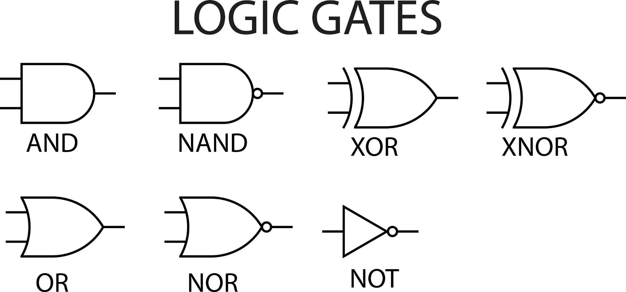
AND Gate
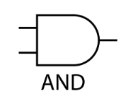
The AND gate outputs a 1 only if all of its inputs are 1.
Think of it as two switches in a series circuit; the light bulb only turns on if both switches are closed.
Input A | Input B | Result |
0 | 0 | 0 |
0 | 1 | 0 |
1 | 0 | 0 |
1 | 1 | 1 |
OR Gate
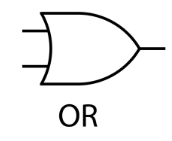
The OR gate outputs a 1 if at least one of its inputs is 1. This is like two switches in a parallel circuit; the light bulb turns on if either switch is closed.
Input A | Input B | Result |
0 | 0 | 0 |
0 | 1 | 1 |
1 | 0 | 1 |
1 | 1 | 1 |
NOT Gate
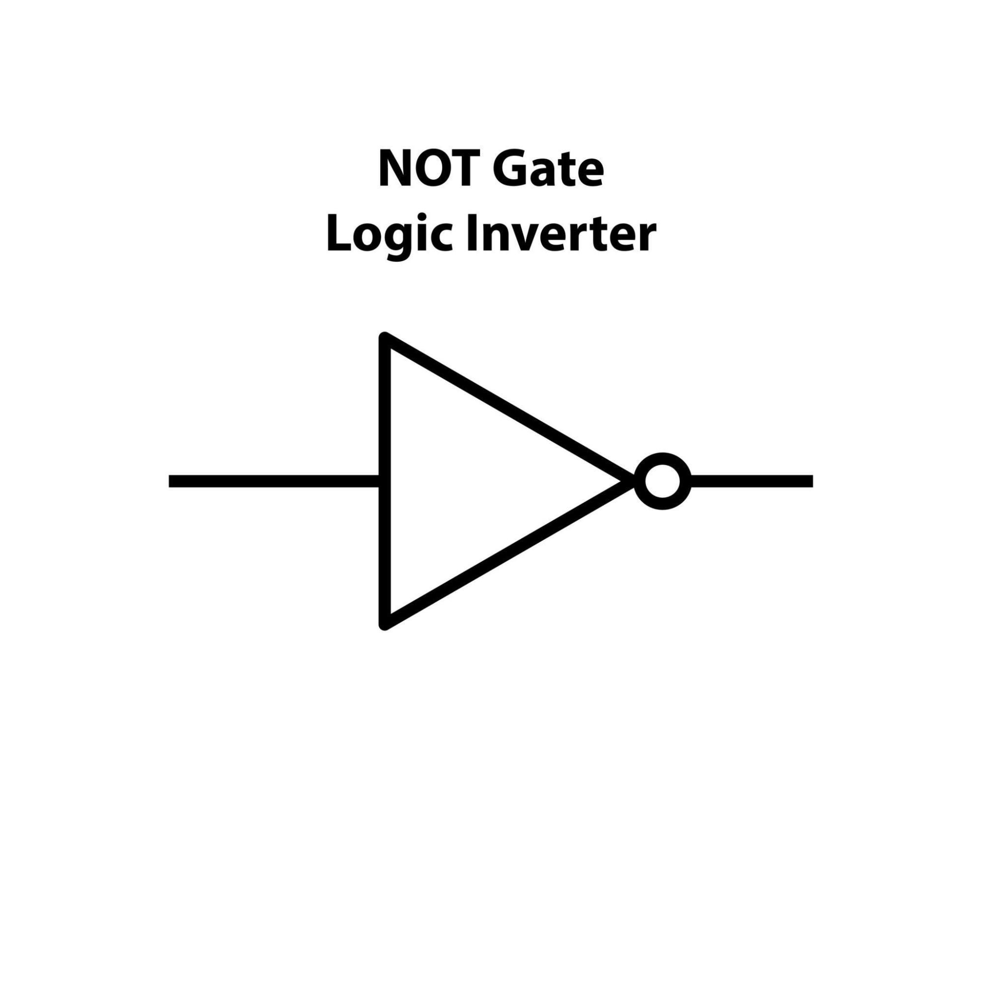
The NOT gate, also called an inverter, is the simplest gate. It has only one input and it reverses the value. A 1 becomes a 0, and a 0 becomes a 1.
Input | Result |
0 | 1 |
1 | 0 |
The Universal Gates
These gates are special because you can create any other type of logic gate by combining them.
NAND Gate (NOT-AND)
The NAND gate works like an AND gate followed by a NOT gate. It outputs a 0 only if all of its inputs are 1; otherwise, the output is 1.
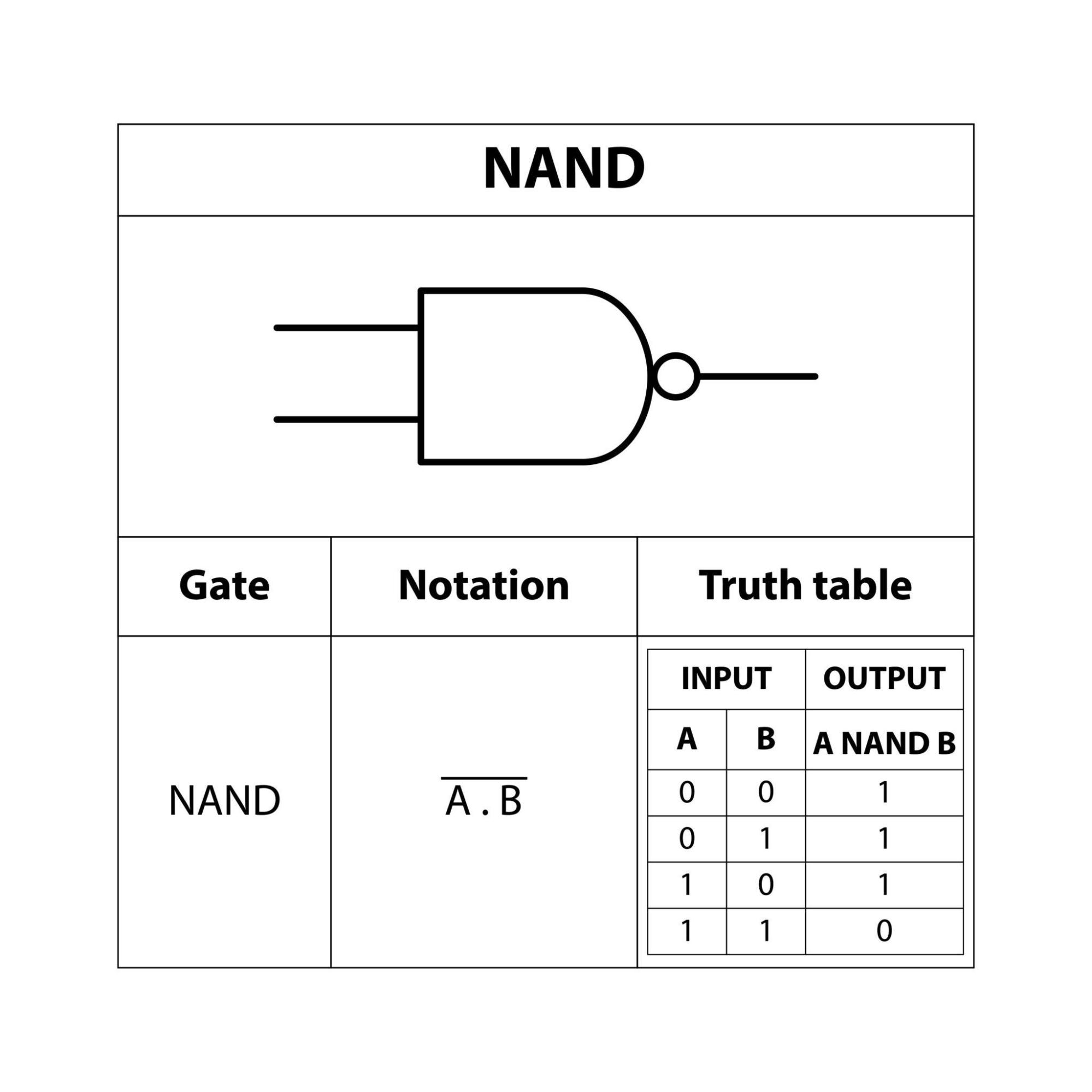
Input A | Input B | Result |
0 | 0 | 1 |
0 | 1 | 1 |
1 | 0 | 1 |
1 | 1 | 0 |
NOR Gate (NOT-OR)
The NOR gate works like an OR gate followed by a NOT gate. It outputs a 1 only if all of its inputs are 0; otherwise, the output is 0.
Input A | Input B | Result |
0 | 0 | 1 |
0 | 1 | 0 |
1 | 0 | 0 |
1 | 1 | 0 |
The Exclusive Gates
These gates are used for more specific logical operations, often in arithmetic circuits.
XOR Gate (Exclusive OR)

The XOR gate outputs a 1 only if the inputs are different. If the inputs are the same, the output is 0. Think of it as asking, "is it one or the other, but not both?"
Input A | Input B | Result |
0 | 0 | 0 |
0 | 1 | 1 |
1 | 0 | 1 |
1 | 1 | 0 |
XNOR Gate (Exclusive NOR)
The XNOR gate is the opposite of the XOR gate. It outputs a 1 only if the inputs are the same. It's essentially an "equality" gate.

Input A | Input B | Result |
0 | 0 | 1 |
0 | 1 | 0 |
1 | 0 | 0 |
1 | 1 | 1 |
Article 3
Whisper to the CPU

How to Speak the Language
The Bare Metal: A Practical Introduction to Assembly Language
Introduction: Speaking Directly to the Silicon
We've journeyed through the foundational history of computing, explored the elegant simplicity of binary, and mastered the art of interpreting machine data through the indispensable lenses of hexadecimal and ASCII. We've even peered into the very "brain" of the machine, understanding how the CPU processes information using fundamental logic gates. Now, the time has come to transcend observation and engage in direct dialogue with the silicon itself. We are no longer merely reading the machine's thoughts; we are learning to whisper commands directly into its core.
This is the realm of Assembly language-the thinnest possible layer between human-readable instruction and the raw, unadulterated machine code that a processor executes. It is the language of unparalleled control, raw power, and for the reverse engineer, the fundamental tool for truly understanding, dissecting, and manipulating software at its deepest level. Mastery of Assembly is not just a skill; it is a gateway to the machine's true essence.
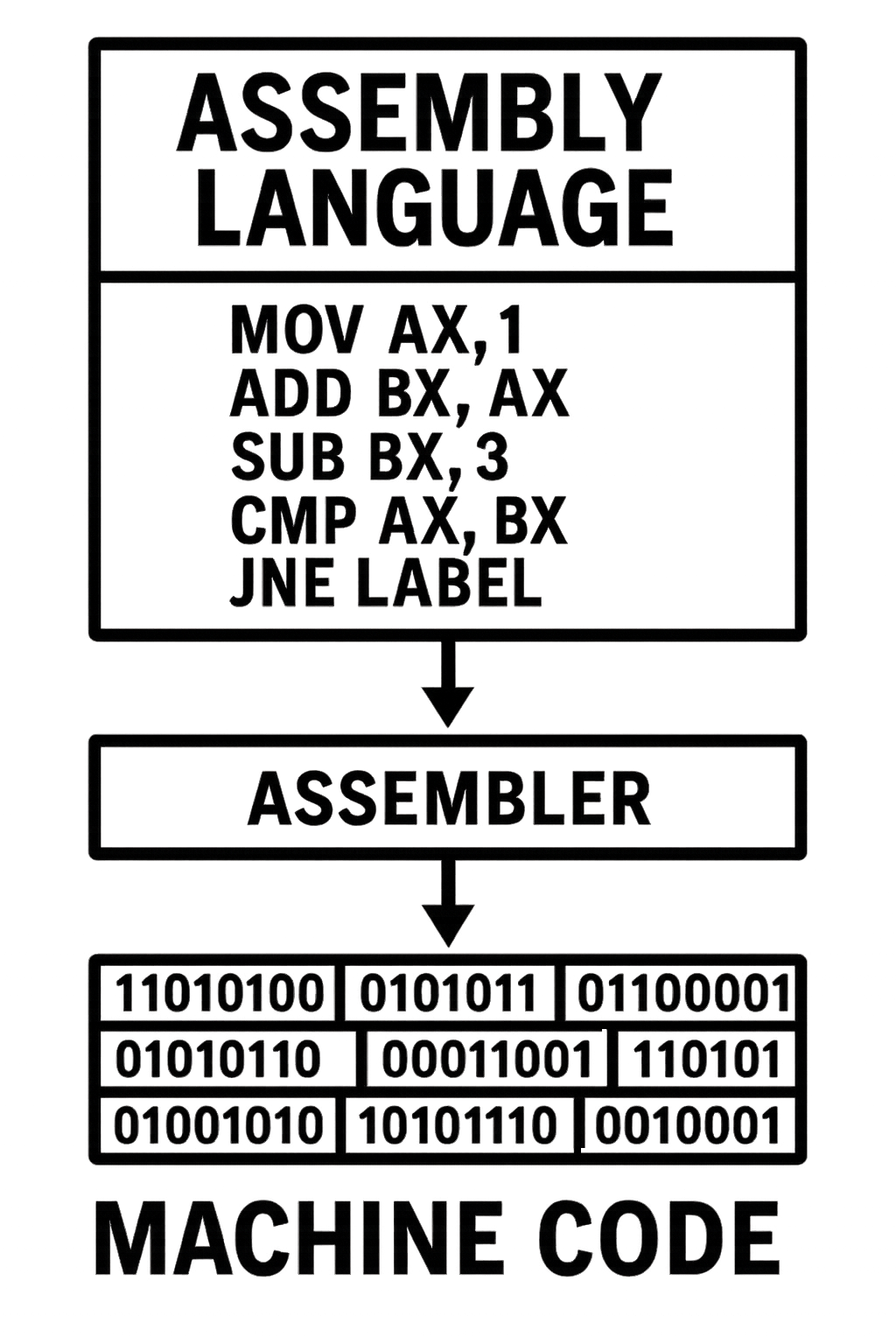
Assembly language is a low-level programming language that has a very strong correspondence to the instruction set architecture (ISA) of a particular computer. It is translated into executable machine code by an assembler.
The Anatomy of an Assembly Program
The CPU's Workbench: Registers
Registers are a small number of extremely fast, on-chip storage locations that the CPU uses for all its immediate work. They are the fastest form of memory available to the CPU, providing a temporary workspace for data and instructions that are actively being processed. Think of them as the CPU's direct workbench, holding the tools and materials needed for the current task.
The main categories of registers include:
- General Purpose Registers (EAX, EBX, ECX, EDX): These are versatile registers used for a wide variety of operations, including arithmetic calculations, data storage, and holding intermediate results.
- Instruction Pointer (EIP): This crucial register holds the memory address of the next instruction the CPU is scheduled to execute, thus controlling the flow of the program.
- Stack Pointers (ESP, EBP): These registers are fundamental for managing the program's call stack. ESP (Stack Pointer) points to the top of the stack, while EBP (Base Pointer) typically points to the base of the current function's stack frame.
- Flags Register (EFLAGS): This register contains individual "flags" or bits that indicate the status of the CPU and the results of previous operations (e.g., whether an arithmetic operation resulted in zero, a carry, or an overflow).
The Program's Blueprint: Sections
Assembly programs are typically organized into distinct sections, each serving a specific purpose in the program's memory layout. These sections help the operating system load and execute the program correctly.
- .text: This section contains the executable code of the program – the actual instructions that the CPU will execute. This is where your assembly language commands reside after being translated into machine code.
- .data: This section is used for initialized data. It stores variables and constants that have predefined values at the time the program starts. For example, a string literal like "Hello, World!" would typically be stored in the .data section.
- .bss: This section is for uninitialized data. It reserves space for variables that will be allocated memory but do not have an initial value defined at compile time. These variables are typically zeroed out by the operating system when the program loads, ensuring a clean slate.
RE Perspective: Memorizing the primary registers is non-negotiable. When you are debugging malware, the registers are your ground truth. EIP tells you what instruction is about to run. EAX almost always holds the result of a function call, telling you if it succeeded or failed. ESP and EBP are your map to the program's stack, letting you see what data is being passed between functions. Watching the registers is the single most important activity in dynamic analysis. |
Core Concepts
Registers
Small, high-speed storage locations within the CPU used to hold data and instructions during program execution.
- General Purpose Registers (EAX, EBX, ECX, EDX): Used for data manipulation and calculations.
- Segment Registers (CS, DS, SS, ES): Used for memory management, locating data in different memory sections.
- Instruction Pointer (EIP): Points to the next instruction to be executed by the CPU.
- Flags Register (EFLAGS): Holds status bits (e.g., carry, zero, negative) after arithmetic or logical operations.
Memory Addressing Modes
Different ways to find data in memory:
- Immediate Addressing: The data is right in the instruction.
- Example: MOV EAX, 10 (put 10 into EAX)
- Register Addressing: The data is in a register.
- Example: MOV EBX, EAX (put EAX's value into EBX)
- Direct Addressing: The instruction directly points to the memory location.
- Example: MOV EAX, [0x1000] (put the value from memory address 0x1000 into EAX)
- Register Indirect Addressing: A register holds the memory address.
- Example: MOV EAX, [EBX] (put the value from the memory address stored in EBX into EAX)
- Base-Indexed Addressing: Add a base register and an index register to get the memory address.
- Example: MOV EAX, [EBX + ECX]
- Scaled-Indexed Addressing: Like base-indexed, but the index register's value is multiplied by 1, 2, 4, or 8.
- Example: MOV EAX, [EBX + ECX*4]
Instructions
Basic operations that the CPU can perform.
- Data Transfer Instructions:
- MOV: Move data between registers, memory, and immediate values.
- PUSH, POP: Manipulate the stack.
- LEA: Load effective address.
- Arithmetic Instructions:
- ADD, SUB: Addition and subtraction.
- MUL, DIV: Multiplication and division.
- INC, DEC: Increment and decrement.
- Logical Instructions:
- AND, OR, XOR, NOT: Bitwise logical operations.
- SHL, SHR: Shift bits left and right.
- Control Flow Instructions:
- JMP: Unconditional jump.
- JE, JNE, JG, JL, etc.: Conditional jumps based on flag status.
- CALL, RET: Subroutine call and return.
- Comparison Instructions:
- CMP: Compares two operands and sets flags.
- TEST: Performs a bitwise AND and sets flags.
Summary
A CPU utilizes high-speed storage locations called Registers for various functions, including General Purpose Registers (EAX, EBX, ECX, EDX) for data manipulation, Segment Registers (CS, DS, SS, ES) for memory management, the Instruction Pointer (EIP) for tracking the next instruction, and the Flags Register (EFLAGS) for storing operation status bits. Memory Addressing Modes dictate how data in memory is accessed, with methods like Immediate, Register, Direct, Register Indirect, Base-Indexed, and Scaled-Indexed Addressing. The CPU executes fundamental Instructions categorized into Data Transfer (MOV, PUSH, POP, LEA), Arithmetic (ADD, SUB, MUL, DIV, INC, DEC), Logical (AND, OR, XOR, NOT, SHL, SHR), Control Flow (JMP, conditional jumps, CALL, RET), and Comparison (CMP, TEST) operations.
RE Perspective: Control flow instructions are the key to understanding a program's logic. An analyst's job is often to trace these jumps. A CMP followed by a JNE (Jump if Not Equal) is an "if/else" statement. A CMP followed by a JL (Jump if Less) inside a function is often a check to see if a buffer is big enough. Malware is filled with complex conditional jumps to hide its behavior. By setting breakpoints at these instructions, you can follow the exact path the malware takes. |
Assembly Language Structure (General)
Sections
Assembly programs are typically divided into sections:
- .data: For initialized data (variables with initial values).
- .bss: For uninitialized data (variables that will be initialized during runtime).
- .text: For executable code (instructions).
Labels
Symbolic names for memory locations or instruction addresses. Used for jumps, calls, and referring to data.
Directives
Instructions for the assembler (not translated into machine code).
- db, dw, dd, dq: Define byte, word, double word, quad word (for defining data).
- RESB, RESW, RESD, RESQ: Reserve byte, word, double word, quad word (for reserving uninitialized memory).
- GLOBAL, EXTERN: For linking with other code modules.
Summary
Assembly programs are organized into sections: .data for initialized data, .bss for uninitialized data (zeroed at runtime for efficiency), and .text for executable code. Labels provide symbolic names for memory locations, aiding readability, control flow (jumps/calls), and data access. Directives guide the assembler, not the CPU. These include data definition directives (db, dw, dd, dq), memory reservation directives (RESB, RESW, RESD, RESQ), and linking directives (GLOBAL, EXTERN) for inter-module communication. These elements are fundamental for structuring, managing, and linking assembly language programs.
Example (x86 Linux Assembly - NASM Syntax)
Lets have a look at this ASM code example.
section .data msg db 'Hello, World!', 0xA, 0xD ; String to print, followed by newline and carriage return len equ $ - msg ; Length of the string section .text global _start ; Entry point for the linker _start: ; Write the string to stdout mov eax, 4 ; The system call number for 'write' mov ebx, 1 ; The destination: stdout (the screen) mov ecx, msg ; The source: our message's address mov edx, len ; The size: how many bytes to write int 0x80 ; Signal the kernel to execute int 0x80 ; Call kernel ; Exit the program mov eax, 1 ; sys_exit system call number mov ebx, 0 ; exit code (0 for success) int 0x80 ; Call kernel |
A Practical Example (Windows): Speaking to the API
In Linux, we communicated with the kernel using system calls. In Windows, the process is different. We don't use the int 0x80 interrupt. Instead, we call functions provided by the operating system in files called Dynamic-Link Libraries (DLLs).
The core concepts to understand are:
- Windows API (WinAPI): This is the collection of all the functions that Windows provides for programmers to use. These functions live inside DLLs like user32.dll (for user interface things like windows and message boxes) and kernel32.dll (for core OS functions like managing memory and processes).
- The Stack: Instead of putting arguments into registers like EAX and EBX, the standard way to call a Windows function (stdcall) is to push the arguments onto the stack in reverse order.
- Null-Terminated Strings: Unlike our Linux example where we had to provide the exact length of our string, most Windows API functions expect strings to be "null-terminated," meaning they end with a byte that is zero.
; Tell the assembler we are using functions defined elsewhere extern MessageBoxA extern ExitProcess ; Tell the linker where to find those functions import MessageBoxA user32.dll import ExitProcess kernel32.dll section .data caption db 'Message', 0 ; The title of our message box, ending with a null byte text db 'Hello, Windows!', 0 ; The text inside our message box, ending with a null byte section .text global _start _start: ; Call the MessageBoxA function ; Arguments are pushed onto the stack in reverse order (right to left)
push 0 ; uType = MB_OK, the style of the message box push caption ; lpCaption = the address of our title string push text ; lpText = the address of our main text string push 0 ; hWnd = 0, no owner window for this message box call MessageBoxA ; Exit the program cleanly push 0 ; uExitCode = 0, exit with a success code call ExitProcess |
Deconstructing the Windows API Call
extern and import: The extern directive tells the assembler, "Don't worry, the code for MessageBoxA exists, but it's in another file." The import directive then tells the linker which DLL to look in at runtime (user32.dll) to find that function.
The .data Section: Notice our strings now end with , 0. This is the crucial null terminator. The MessageBoxA function will read from the text and caption memory addresses until it hits that zero byte. We no longer need to calculate the length.
Calling MessageBoxA: The documentation for MessageBoxA shows it needs four arguments. We push them onto the stack in reverse order:
- push 0: The last argument is the "type" flag. 0 is the default for a simple "OK" button.
- push caption: The third argument is a pointer to the caption string.
- push text: The second argument is a pointer to the main text string.
- push 0: The first argument is the "owner window handle." 0 means it's a standalone window.
- call MessageBoxA: This instruction pushes the return address onto the stack and then jumps to the MessageBoxA code inside user32.dll.
Exiting with ExitProcess: Instead of a system call, we call the ExitProcess function from kernel32.dll. We push 0 onto the stack for the exit code and call the function to terminate the program cleanly.
This Windows example introduces a critical concept: using the stack to pass arguments to functions. This is fundamental to all reverse engineering on Windows. Your notes already have great material on the stack pointers (ESP and EBP).
Since most examples in this book will be Windows-focused to keep things relevant and concise, I'll do my best to point out the differences between operating systems whenever I can.
Conclusion: The Building Blocks of Execution
The CPU's inner workings really depend on Registers, Memory Addressing Modes, and an Instruction Set to run programs and handle data efficiently.
Registers are super-fast storage spots right inside the CPU, and each one has a specific job:
- General Purpose Registers (EAX, EBX, ECX, EDX): These are for messing around with data.
- Segment Registers (CS, DS, SS, ES): They help out with memory management.
- Instruction Pointer (EIP): This guy keeps track of where the next instruction is.
- Flags Register (EFLAGS): It holds all the status bits after operations happen.
Memory Addressing Modes are basically how the CPU gets to data in memory. Here are some of them:
- Immediate Addressing: The data value is right there in the instruction itself.
- Register Addressing: The data is chilling in a CPU register.
- Direct Addressing: The instruction just tells you the exact memory address of the data.
- Register Indirect Addressing: A register holds the memory address for the data.
- Base-Indexed Addressing: This combines a base register and an index register to figure out the memory address.
- Scaled-Indexed Addressing: Pretty similar to base-indexed, but with an extra scaling factor applied to the index.
The Instruction Set is a complete list of everything the CPU can do, broken down like this:
- Data Transfer Instructions (MOV, PUSH, POP, LEA): These are for moving data between registers and memory.
- Arithmetic Instructions (ADD, SUB, MUL, DIV, INC, DEC): For all your math calculations.
- Logical Instructions (AND, OR, XOR, NOT, SHL, SHR): For playing around with bits.
- Control Flow Instructions (JMP, conditional jumps, CALL, RET): For managing how your program runs.
- Comparison Instructions (CMP, TEST): For comparing stuff and setting flags based on the outcomes.
Getting how all these pieces fit together, especially registers and the program stack, is really key to understanding low-level hardware and making your programs run faster. Our next article will dive deeper into registers and the stack, showing how they team up to manage data and function calls.
Deepdive - General Purpose Registers
This table shows the general registers,
It's highly recommended to memorize them.
Type | Examples | Notes |
General Purpose | EAX, EBX, ECX, EDX | Utilized for arithmetic, loops, and return values |
Stack / Pointer | ESP, EBP, EIP | Responsible for stack control and execution flow |
Index (String Ops) | ESI, EDI | Employed in memory copying and repetition operations |
Segment Registers | CS, DS, SS, FS, GS, ES | Pertain to the legacy segmented memory model |
Flags Register (EFLAGS) | ZF, CF, OF, SF, etc. | Automatically configured subsequent to arithmetic/logical operations |
Register Sizes and Splits
Register | 32-bit | 16-bit | High 8-bit | Low 8-bit |
EAX | EAX | AX | AH | AL |
EBX | EBX | BX | BH | BL |
Memorizing assembly registers is paramount for programmers and reverse engineers alike. For programmers, it's the key to understanding how data flows within the CPU, optimizing code, and directly interfacing with hardware. For reverse engineers and malware analysts, intimate knowledge of registers is indispensable for dissecting program execution, identifying critical data, and uncovering malicious intent, as registers are often the first place to look for clues in a program's behavior. Without this foundational knowledge, navigating the low-level world of assembly becomes an almost impossible task.
Let us now examine each register individually, detailing its usage and unique properties.
General Registers:
- EAX – Extended Accumulator Register
- The EAX register is a highly versatile 32-bit register, serving as the primary accumulator for arithmetic and logic operations in x86 architecture. It's frequently used for operations such as addition, subtraction, multiplication, and division. Beyond simple calculations, EAX is a crucial register for storing the return values of functions, making it essential for inter-procedural communication. Its direct involvement in many CPU instructions means it's often optimized for performance in these roles.
- EBX – Extended Base Register
- While also a general-purpose 32-bit register, EBX is particularly useful for holding base addresses. This means it can store the starting memory address of a data structure or an array, allowing other registers or offsets to access specific elements relative to this base. Its flexibility also allows it to be used for general data storage when not serving its specialized base addressing role.
- ECX – Extended Counter Register
- (Not shown in the original text but highly relevant for a complete understanding) The ECX register is a 32-bit register predominantly used as a counter, especially in loop operations. Instructions like `LOOP` decrement ECX and jump if ECX is not zero, making it integral for controlling iterations. Additionally, it plays a vital role in shift and rotate instructions, where it specifies the number of bits to shift or rotate.
- EDX – Extended Data Register
- The EDX register is a 32-bit general-purpose register often used in conjunction with EAX. In multiplication operations, for instance, if the product exceeds the 32-bit capacity of EAX, the higher-order bits are stored in EDX, forming a 64-bit result (EDX:EAX). Similarly, in division, EAX holds the dividend and EDX holds the remainder. EDX is also frequently employed in I/O operations, such as specifying port addresses for data transfer.
Pointer/Index Registers:
- ESP – Extended Stack Pointer
- The ESP is a critical 32-bit register that always points to the very top (the most recently pushed item) of the program's stack. It is automatically managed by several instructions: `PUSH` decrements ESP (as the stack grows downwards in memory) and stores data, while `POP` retrieves data and increments ESP. `CALL` instructions push the return address onto the stack and modify ESP, and `RET` instructions pop the return address and restore ESP. Direct manipulation of ESP is generally discouraged, as it can easily corrupt the stack and lead to program crashes.
- EBP – Extended Base Pointer
- The EBP register, a 32-bit pointer, is primarily used to point to the base of the current stack frame. A stack frame is the portion of the stack allocated for a function's local variables, parameters, and saved register values. By establishing a fixed reference point within the stack frame, EBP allows for efficient and consistent access to function parameters passed on the stack and to local variables defined within the function. While ESP moves constantly, EBP remains relatively fixed for the duration of a function's execution, providing a stable reference.
Instruction Pointer:
- EIP – Extended Instruction Pointer
- The EIP is a crucial 32-bit register that holds the memory address of the next instruction the CPU will execute. It dictates the flow of program execution. Unlike other registers, EIP cannot be directly modified by common data manipulation instructions. Its value is implicitly changed by control flow instructions such as: `JUMP` (unconditional transfer of control), `CALL` (jumps to a subroutine and pushes the return address onto the stack), and `RET` (pops a return address from the stack and transfers control back). Understanding EIP is fundamental to comprehending how programs execute step-by-step and how control is transferred between different parts of a program.
The provided text is a table listing 32-bit and 64-bit registers used in assembly language, categorized by their purpose.
It details general-purpose registers (EAX/RAX, EBX/RBX, ECX/RCX, EDX/RDX), index registers (ESI/RSI, EDI/RDI), stack registers (ESP/RSP, EBP/RBP), and the control flow register (EIP/RIP), explaining their names and primary usages. Key usages include arithmetic, loop counters, multiply/divide operations, string/memory operations, and stack management.
32-bit Reg | 64-bit Reg | Category | Name | Purpose / Usage |
EAX | RAX | General Purpose | Accumulator | Main register for arithmetic, logic, and return values from functions |
EBX | RBX | General Purpose | Base | Flexible usage; often used as base register |
ECX | RCX | General Purpose | Counter | Used for loop counters, rep instructions |
EDX | RDX | General Purpose | Data | Used with EAX/RAX in multiply/divide, I/O |
ESI | RSI | Index | Source Index | Used in string/memory operations (e.g., movs, lods) |
EDI | RDI | Index | Destination Index | Paired with ESI, used in memory/string operations |
ESP | RSP | Stack | Stack Pointer | Points to the top of the stack |
EBP | RBP | Stack | Base Pointer | Marks base of the current stack frame |
EIP | RIP | Control Flow | Instruction Pointer | Points to the next instruction to execute |
What are segments in x86?
Segments represent a legacy memory management system that emerged from the foundational Intel 8086 architecture. This 16-bit CPU design introduced a method to partition computer memory into distinct, manageable regions. The primary purpose was to overcome the inherent limitations of early processors and enable them to access larger amounts of available RAM.
In the original segmented memory model, memory was typically divided into four core segments, each serving a specific purpose:
- Code Segment: This region was dedicated to storing the executable instructions of a program. When the CPU needed to fetch an instruction, it would look within the code segment.
- Data Segment: This area was used to hold the variables and other data that a program actively manipulated. This included global variables, static variables, and other program-specific data structures.
- Stack Segment: The stack is a crucial data structure used for temporary storage during program execution. The stack segment facilitated the management of function calls, local variables, and return addresses. Operations like `PUSH` and `POP` directly interact with this segment.
- Extra Segment: This was a general-purpose segment that could be used for various additional data or operations. Its flexibility allowed programmers to use it for secondary data storage, string manipulations, or other auxiliary purposes as needed.
Rationale for Segmented Memory: Overcoming Early CPU Limitations
The development of segmented memory was a direct response to a significant architectural constraint of early central processing units. These CPUs were primarily limited to accessing 64 KB of memory per register. This meant that while larger amounts of RAM might have been physically present in the system, the CPU could only directly address a relatively small chunk at any given time using a single register.
To overcome this seemingly restrictive 64 KB addressing limit and allow 16-bit code to utilize up to 1MB of memory (the maximum addressable memory for the 8086), Intel devised the segmented memory model. This innovative approach employed a two-part addressing scheme that combined a segment register's value with an offset value to calculate a "real" or physical memory address. The calculation was as follows:
Segment Register Value × 16 + Offset Value = Real Memory Address
Here's how it worked:
- Segment Register: These 16-bit registers (e.g., CS for Code Segment, DS for Data Segment, SS for Stack Segment, ES for Extra Segment) held a "segment base" address. The value in a segment register was implicitly multiplied by 16 (or shifted left by 4 bits) to derive a 20-bit segment base address. This effectively created a 16-byte paragraph boundary.
- Offset Value: This 16-bit value represented the distance (offset) from the beginning of the segment to the specific memory location being accessed.
By combining a 16-bit segment register (which provided a 20-bit base address) with a 16-bit offset, the 8086 CPU was able to generate a 20-bit physical memory address. This allowed access to 2^20 bytes, or 1,048,576 bytes (1MB) of memory, significantly expanding the addressable range beyond the 64 KB register limitation.
While segments were a crucial innovation for their time, enabling early systems to manage more memory, they also introduced complexities like segment overlaps and the need for careful management of segment registers.
As computing evolved, more sophisticated memory management units (MMUs) and flat memory models largely superseded the segment-based approach, though vestiges of segmentation can still be found in protected mode operation within modern x86 architectures.
Segment | Usage | Key Offsets (Windows 32-bit) |
FS | Thread-local data (TEB) | 🔹 0x18: Pointer to TEB |
🔹 0x1C: Pointer to PEB | ||
🔹 0x04: Stack limit | ||
🔹 0x08: Stack base | ||
🔹 0x24: Thread ID | ||
🔹 0x2C: Pointer to TLS array | ||
GS | Not utilized on Windows x86 | Reserved or undefined; not employed by Windows in this context |
CS | Code execution | No data - solely references the segment base of code. No offsets are employed. |
DS | Data (default) | No fixed offsets - references the data segment; access is dependent on program execution. |
SS | Stack | No fixed offsets - automatically utilized with ESP/EBP; not accessed manually. |
ES | String/memory operations | Employed in specialized instructions (e.g., movs, scas, stos); lacks a readable structure. |
FS – Thread-local / TEB Access (Windows x86)
Example:
mov eax, fs:[0x18] ; Retrieve TEB pointer
mov eax, [eax + 0x24] ; Obtain Thread ID from TEB
Result:
- EAX will contain the current thread's unique identifier.
- This is frequently employed in malware, anti-debugging techniques, and system-level pamming.
GS – Not Utilized in 32-bit Windows, However, an Example is Provided
Example:
mov eax, gs:[0x00] ; Attempt to access address 0 in Ga
Segment (typically invalid on . windows)
Result:
- This operation is highly likely to cause an exception or undefined behavior.
- On Linux or x64 architectures, this would facilitate access to Thread-Local Storage (TLS) or kernel information.
Disregard GS on Windows 32-bit unless engaged in operating system development or 64-bit kernel manipulations.CS – Code Segment (Execution Context)
Example:
push cs
pop ax
Result:
- AX will subsequently hold the current code segment selector.
- This is primarily relevant in ring transition code or highly low-level execution models.
DS – Data Segment (Default for Most Data Access Operations):
mov eax, ds:[0x00402000]
Result:
- EAX receives the value stored at the linear address 0x00402000.
- This is functionally equivalent to `mov eax, [0x00402000]` as DS is the default segment.
- This segment is utilized constantly, albeit implicitly.
SS – Stack Segment:
mov eax, ss:[esp] ; Read the value at the top of the stack
Result:
- EAX obtains the value located at the top of the stack.
- This is functionally identical to `mov eax, [esp]`.
- SS is implicitly assumed for all stack-related instructions (e.g., `push`, `pop`).
ES – Extra Segment (Used with String Operations):
cld ; Clear direction flag (for forward copying)
mov cx, 10 ; Specify 10 bytes for copying
mov si, source
mov di, dest
rep movsb ; Copy CX bytes from DS:SI to ES:DI
Result:
- 10 bytes are copied from `[ds:si]` to `[es:di]`.
- The ES segment must be configured appropriately prior to execution.
- This is employed in string/memory copying operations, primarily in legacy contexts.
Concise Summary Table
Segment | Example | Result / Function |
FS | `mov eax, fs:[0x18]` | Retrieves the TEB (Thread Environment Block) pointer. |
GS | `mov eax, gs:[0x00]` | Invalid in Windows x86 - likely leads to a crash or indeterminate data. |
CS | `push cs / pop ax` | Loads the code segment selector into AX. |
DS | `mov eax, ds:[0x00402000]` | Loads data from memory (equivalent to `[addr]`). |
SS | `mov eax, ss:[esp]` | Reads the value at the top of the stack (equivalent to `[esp]`). |
ES | `rep movsb` (utilizes ES:DI) | Copies bytes using a string operation with a segment override. |
What are constants/flags?
In assembly language and low-level programming, "constants" and "flags" generally refer to two distinct but related concepts, often used in the context of operating system interactions or specific CPU behaviors.
What are Constants?
In this context, "constants" often refer to fixed, predefined numerical values that represent specific options, settings, or identifiers for functions and operations, particularly when interfacing with the operating system (e.g., Windows API calls) or hardware. They are symbolic names given to these numeric values to make code more readable and maintainable.
These constants are not part of the assembly language syntax itself in the same way instructions are. Instead, they are typically defined in header files (e.g., in C/C++ development for Windows) that are then referenced by the assembler or compiler. When you see them used in assembly examples, it implies that the corresponding numeric value is being used directly or via a symbolic definition in the assembly source.
For instance, MEM_COMMIT (0x1000) is a constant. When you use it in an assembly instruction like push 0x1000, you are pushing the value of the constant, not its symbolic name.
What are Flags?
CPU Flags, often referred to as Status Flags, are single-bit indicators residing within a dedicated CPU register. In the x86 architecture, this is typically the EFLAGS register (or RFLAGS in 64-bit systems). These flags serve as a critical feedback mechanism, automatically set or cleared by the CPU after the execution of arithmetic or logical operations. They provide immediate insight into the outcome of these operations, such as whether a result was zero, negative, or caused an overflow.
How They Work:
- Automatic Manipulation: When an instruction like ADD, SUB, CMP (compare), or TEST is executed, the CPU analyzes the result and updates the relevant flags. For instance, if the sum of two numbers is zero, the Zero Flag (ZF) is set to 1; otherwise, it's cleared to 0.
- Conditional Program Flow: Programmers leverage these flags to control the program's execution path. Conditional jump instructions are the primary tool for this. These instructions (e.g., JE - Jump if Equal, JNE - Jump if Not Equal, JG - Jump if Greater) inspect the state of specific flags and, based on their values, either transfer control to a different part of the code or allow execution to continue sequentially. This enables the implementation of if-else statements, loops, and other decision-making structures at the assembly level.
- Interrupts and Exceptions: CPU flags can also play a role in handling interrupts and exceptions, providing information about the processor's state at the time of an event.
1.Key CPU Flags and Their Significance:
- Zero Flag (ZF):
- Description: Set to 1 if the result of an operation is exactly zero. Cleared to 0 otherwise.
- Use Case: Often used after a CMP instruction to determine if two values are equal, or after an arithmetic operation to check for a zero result.
- Carry Flag (CF):
- Description: Set to 1 if an arithmetic operation generates a carry out of the most significant bit (for addition) or a borrow into the most significant bit (for subtraction). Cleared to 0 otherwise.
- Use Case: Essential for multi-precision arithmetic, allowing operations on numbers larger than the CPU's native word size. Also used in some rotate instructions.
- Sign Flag (SF):
- Description: Set to 1 if the most significant bit of the result is 1, indicating a negative number in two's complement representation. Cleared to 0 if the most significant bit is 0, indicating a non-negative number.
- Use Case: Used to determine the sign of a signed arithmetic result.
- Overflow Flag (OF):
- Description: Set to 1 if an arithmetic operation results in a value that is too large (positive overflow) or too small (negative overflow) to be represented by the destination operand's data type, assuming signed arithmetic. This means the sign of the result is incorrect.
- Use Case: Crucial for detecting errors in signed arithmetic, preventing incorrect calculations due to data type limitations.
- Parity Flag (PF):
- Description: Set to 1 if the least significant byte of the result contains an even number of set bits (even parity). Cleared to 0 if it contains an odd number of set bits (odd parity).
- Use Case: Historically used for basic error checking in data transmission, though less common in modern general-purpose computing.
- Auxiliary Carry Flag (AF):
- Description: Set to 1 if there is a carry or borrow from bit 3 to bit 4 (the lower nibble to the upper nibble) of the result.
- Use Case: Primarily used in BCD (Binary Coded Decimal) arithmetic.
- Direction Flag (DF):
- Description: Controls the direction of string operations. When DF is 0, string instructions (like MOVSB, STOSW) process data from lower addresses to higher addresses (incrementing pointers). When DF is 1, they process from higher to lower addresses (decrementing pointers).
- Use Case: Essential for efficient string manipulation, allowing forward or reverse processing of data blocks. Programmers explicitly set or clear this flag using CLD (Clear Direction Flag) or STD (Set Direction Flag) instructions.
- Interrupt Flag (IF):
- Description: Controls whether the CPU responds to maskable external interrupts. If IF is 1, maskable interrupts are enabled; if 0, they are disabled.
- Use Case: Critical for managing interrupt service routines and ensuring proper system responsiveness while preventing unwanted interruptions during critical code sections.
2. Bit Flags (Control/Option Flags)
In contrast to CPU Flags, Bit Flags are not automatically managed by the CPU based on arithmetic results. Instead, they are single bits (or combinations of bits) within a general-purpose numerical value, typically an integer. Each bit position within this value represents an independent Boolean option, setting, or state. This technique allows multiple distinct options to be compactly stored and manipulated within a single variable.
How They Work:
- Bitwise Operations: Bit flags are manipulated using bitwise logical operations.
- Setting a Flag (Turning an option ON): A specific bit is turned on (set to 1) by performing a bitwise OR operation (|) between the current flag value and a mask where only the desired bit is set.
- Example: flags = flags | OPTION_A;
- Clearing a Flag (Turning an option OFF): A specific bit is turned off (set to 0) by performing a bitwise AND operation (&) between the current flag value and the bitwise NOT (~) of the desired flag mask.
- Example: flags = flags & ~OPTION_A;
- Checking a Flag (Is an option ON?): To determine if a particular option is enabled, a bitwise AND operation is performed between the current flag value and the mask for that option. If the result is non-zero (equal to the mask itself), the option is set.
- Example: if (flags & OPTION_A) { // OPTION_A is enabled }
- Toggling a Flag: A bit can be flipped (0 to 1, or 1 to 0) using a bitwise XOR operation (^).
- Example: flags = flags ^ OPTION_A;
- Constants as Masks: Each bit flag is typically defined as a unique power-of-two constant (e.g., 0x01, 0x02, 0x04, 0x08), which means only one bit is set in its binary representation. This allows them to act as distinct masks for individual options.
- Function Parameters: Bit flags are commonly used as parameters in function calls, especially in API (Application Programming Interface) calls. A function might accept a single integer parameter, where each bit in that integer instructs the function to behave in a specific way or apply a certain configuration. The function then internally checks which bits are set to determine its execution path.
Example Scenario:
To simplify, lets imagine its a C++ code,
Imagine a function to open a file that can have various options:
// Define bit flag constants const int OPEN_READ_ONLY = 0x01; // Binary 0001 const int OPEN_CREATE_IF_NOT_EXIST = 0x02; // Binary 0010 const int OPEN_APPEND_MODE = 0x04; // Binary 0100 // User wants to open a file for reading, and create it if it doesn't exist int file_options = OPEN_READ_ONLY | OPEN_CREATE_IF_NOT_EXIST; // file_options will be 0x03 (Binary 0011) // Pass this value to the file opening function openFile("my_document.txt", file_options); // Inside openFile function: void openFile(const char* filename, int options) { if (options & OPEN_READ_ONLY) { // Open file in read-only mode } if (options & OPEN_CREATE_IF_NOT_EXIST) { // Check if file exists, create if not } if (options & OPEN_APPEND_MODE) { // This option was not set } } |
Advantages of Bit Flags:
- Memory Efficiency: Multiple Boolean values can be stored in a single byte or word, saving memory compared to using separate Boolean variables for each option.
- Concise API Design: Functions can accept a single parameter to configure multiple behaviors, simplifying their interface.
- Flexibility: Options can be easily combined or changed by simply altering the bitwise operations.
Flags summary
In summary, while both CPU Flags and Bit Flags involve the manipulation of individual bits, their purpose, mechanism of operation, and typical use cases are quite different. CPU Flags provide immediate status information about CPU operations and are primarily used for conditional program flow, whereas Bit Flags are a programming idiom for compactly representing and managing multiple independent options or states using bitwise logic. Both are fundamental tools for low-level control and efficient programming.
In assembly language, "flags" are a really big deal, and they come in two main flavors: CPU Flags and Bit Flags. If you want to be good at low-level programming and working with systems, you really need to get the difference between them.
1. CPU Flags (Status Flags)
Think of these as tiny little switches in a special CPU register (like the EFLAGS register in x86). They flip on or off automatically after you do some math or logic, telling you what happened. Programmers then use these flags with conditional jump instructions (like JE, JNE, JG) to make the program go different ways depending on the results. Here are some examples:
- Zero Flag (ZF): This one turns on if your operation resulted in zero.
- Carry Flag (CF): This lights up if your math operation overflowed (for addition) or underflowed (for subtraction) past the biggest bit.
- Sign Flag (SF): If your operation came out negative, this flag will be on.
- Overflow Flag (OF): This kicks in if your arithmetic operation went beyond what the destination could hold, either too big or too small.
- Direction Flag (DF): This little guy controls which way string operations go (counting up or down).
2. Bit Flags (Control/Option Flags)
These are like individual little switches (or groups of them) packed into a single number (often a constant). They're used to represent a bunch of independent on/off options or states. Each bit position stands for a specific option. You can turn on multiple options at once by combining these bits using bitwise OR operations. Then, when you send this combined value to a function (like an API call), the function checks which bits are set to decide how it should behave.
Thread Creation Flags
These are constants passed to functions like CreateThread or CreateRemoteThread in Windows. Each flag (a specific bit within the combined value) dictates a particular aspect of how the new thread should be created.
- CREATE_SUSPENDED (0x00000004): This is a bit flag. When this bit is set in the dwCreationFlags parameter of CreateThread, it instructs the operating system to create the new thread in a suspended state. This means the thread's execution is paused immediately after creation, and it will not run until explicitly resumed (e.g., by ResumeThread). This is often used in techniques like process hollowing or for setting up the thread's environment before it begins execution.
Memory Allocation Flags
These are constants used with memory management functions like VirtualAlloc or VirtualAllocEx in Windows. They tell the operating system how to allocate and manage a region of virtual memory.
- MEM_COMMIT (0x1000): This flag tells the system to allocate physical storage (RAM or page file space) for the specified region of virtual memory. Without MEM_COMMIT, you might only reserve the virtual address space (MEM_RESERVE).
- MEM_RESERVE (0x2000): This flag reserves a contiguous block of virtual address space for your process. It does not allocate physical memory at this point, only reserves the addresses so no other allocation can use them. You would typically commit physical memory later.
- MEM_RELEASE (0x8000): This flag is used with VirtualFree to decommit and release an entire reserved memory region back to the system.CREATE_SUSPENDED (0x00000004): This flag creates a suspended thread, pausing execution until resumed. Useful for process hollowing or environment setup.
In short
Constants for Windows memory management functions (e.g., VirtualAlloc).
MEM_COMMIT (0x1000): Allocates physical storage (RAM/page file) for virtual memory.
MEM_RESERVE (0x2000): Reserves virtual address space without allocating physical memory.
MEM_RELEASE (0x8000): Used with VirtualFree to decommit and release reserved memory.
Memory Protection Flags
These flags determine the access rights for a region of memory, such as whether it can be read from, written to, or executed. They are often combined using bitwise OR.
- PAGE_READWRITE (0x04): This flag indicates that the memory region can be both read from and written to. It is not executable.
- PAGE_EXECUTE_READWRITE (0x40): This flag indicates that the memory region can be read from, written to, and executed. This is a powerful permission often used for injecting shellcode or dynamically generated code, as it allows the data (the shellcode) to be treated as executable instructions.
- PAGE_NOACCESS (0x01): This flag means that no access (read, write, or execute) is allowed to the memory region. Any attempt to access it will result in an access violation (a crash). This is sometimes used as an anti-debugging technique or to guard against buffer overflows by marking regions adjacent to buffers as no-access.
We will outline seven categories of flags used in Windows programming, primarily related to memory management, process/thread control, file operations, and GUI elements.
The flag categories are:
- Memory Allocation Type Flags: Control memory reservation, commitment, and deallocation (e.g., MEM_COMMIT, VirtualAlloc).
- Memory Protection Flags: Dictate read, write, and execute permissions within memory (e.g., PAGE_READWRITE, VirtualProtect).
- Access Rights Flags: Define permissions for obtaining handles to system objects like processes, threads, and files (e.g., PROCESS_ALL_ACCESS, OpenProcess).
- Thread Creation Flags: Control the behavior of newly created threads (e.g., CREATE_SUSPENDED, CreateThread).
- File & Section Mapping Flags: Determine how files or sections are mapped into memory (e.g., SEC_COMMIT, MapViewOfFile).
- Window Styles / GDI Flags: Relevant for GUI-related functionalities (e.g., WS_EX_LAYERED, CreateWindowEx).
- Registry Access Flags: Specify permissions for interacting with registry keys and values (e.g., KEY_READ, RegOpenKeyEx).
Below is a table that summarizes the various types of flags discussed:
Type of Flag | Description | Examples |
CPU Flags | Individual bits within a CPU register (e.g., EFLAGS in x86) that reflect the outcome of previous arithmetic or logical operations, used for conditional program flow. | Zero Flag (ZF), Carry Flag (CF), Sign Flag (SF), Overflow Flag (OF) |
Bit Flags | Single bits (or combinations of bits) within a numerical value that represent a set of independent Boolean options or states. These can be combined using bitwise OR and passed to functions to control their behavior. | Thread Creation Flags, Memory Allocation Flags, Memory Protection Flags |
Thread Creation Flags | Constants passed to functions like CreateThread or CreateRemoteThread in Windows, dictating how a new thread should be created. | CREATE_SUSPENDED (0x00000004) |
Memory Allocation Flags | Constants used with memory management functions like VirtualAlloc or VirtualAllocEx in Windows, determining how a region of virtual memory is allocated and managed. | MEM_COMMIT (0x1000), MEM_RESERVE (0x2000), MEM_RELEASE (0x8000) |
Memory Protection Flags | These flags determine the access rights for a region of memory, such as whether it can be read from, written to, or executed. They are often combined using bitwise OR. | PAGE_READWRITE (0x04), PAGE_EXECUTE_READWRITE (0x40), PAGE_NOACCESS (0x01) |
Flags all around
1. Memory Allocation Type Flags
These flags govern the reservation, commitment, and deallocation of memory regions.
Associated APIs: VirtualAlloc, VirtualAllocEx, NtAllocateVirtualMemory, VirtualFree
Examples:
MEM_COMMIT, MEM_RESERVE, MEM_RELEASE
Key Values:
0x1000, 0x2000, 0x8000
2. Memory Protection Flags
These flags dictate the permissible operations (read, write, execute) within allocated memory.
Associated APIs: VirtualAlloc, VirtualProtect, NtProtectVirtualMemory
Examples:
PAGE_READWRITE, PAGE_EXECUTE_READWRITE, PAGE_NOACCESS
Key Values:
0x04, 0x40, 0x01
3. Access Rights Flags
These flags define the permissions granted when obtaining handles to system objects such as processes, threads, files, and registry keys.
Associated APIs: OpenProcess, OpenThread, CreateFile, RegOpenKeyEx
Examples:
PROCESS_ALL_ACCESS, GENERIC_READ, KEY_QUERY_VALUE
Key Values:
0x1FFFFF, 0x80000000, 0x20019
4. Thread Creation Flags
These flags control the behavior of newly created threads.
Associated APIs: CreateThread, CreateRemoteThread, NtCreateThreadEx
Examples:
0x00000004 = CREATE_SUSPENDED
Less Common:
STACK_SIZE_PARAM_IS_A_RESERVATION, etc.
5. File & Section Mapping Flags
These flags determine how files or sections are mapped into memory.
Associated APIs: CreateFileMapping, MapViewOfFile, NtMapViewOfSection
Examples:
SEC_COMMIT, SEC_IMAGE, FILE_MAP_WRITE, FILE_MAP_EXECUTE
6. Window Styles / GDI Flags
These flags are primarily relevant for malware exhibiting Graphical User Interface (GUI), overlay, or screenshot functionalities.
Associated APIs: CreateWindowEx, SetWindowLong, GetDC, etc.
Examples: WS_EX_LAYERED, SW_HIDE, WS_VISIBLE
7. Registry Access Flags
These flags specify permissions for interacting with registry keys and values.
Associated APIs: RegOpenKeyEx, RegSetValueEx
Examples: KEY_READ, KEY_WRITE, KEY_ALL_ACCESS
Summary of Essential Flag Types
Type | Representative APIs |
MEM_* | VirtualAlloc, VirtualAllocEx |
PAGE_* | VirtualProtect, VirtualAlloc |
PROCESS_, GENERIC_ | OpenProcess, CreateFile, RegOpenKeyEx |
CREATE_* | CreateThread, CreateRemoteThread |
SEC_, FILE_MAP_ | MapViewOfFile, CreateFileMapping |
Article 4: The Stack - The CPU's Short-Term Memory
1. Introduction: Why the Stack Matters
We've seen how to give the CPU commands and how to call functions from the Windows API. But when we call MessageBoxA, how does the computer know where to pass our arguments? And after the message box closes, how does the program know where to resume execution? The answer to both questions is the stack.
The stack is a simple, temporary storage area in memory that is essential for managing function calls, passing data between them, and storing local variables. For a reverse engineer, the stack is a treasure map. By examining it, you can reconstruct what a function does, what data it's operating on, and how it interacts with the rest of the program. Mastering the stack is non-negotiable.
2. Stack Fundamentals
The stack operates on a Last-In, First-Out (LIFO) principle, much like a stack of plates. The last item added to the stack is the first one to be removed. This principle makes it incredibly efficient for managing temporary data.
Key Characteristics of the Stack:
- LIFO Structure: Data is pushed onto the top of the stack and popped off the top.
- Dynamic Allocation: The stack grows and shrinks dynamically as functions are called and return, or as local variables are created and destroyed.
- Stack Pointer (ESP/RSP): A dedicated register (ESP in 32-bit, RSP in 64-bit) always points to the "top" of the stack, indicating the most recently added item.
- Base Pointer (EBP/RBP): Another register (EBP in 32-bit, RBP in 64-bit) typically points to the "base" of the current function's stack frame, providing a stable reference point for accessing local variables and arguments.
- Downward Growth: In x86/x64 architectures, the stack traditionally "grows downwards" in memory, meaning that pushing an item onto the stack decreases the stack pointer's value, and popping an item increases it.
Common Stack Operations:
- PUSH: Adds data to the top of the stack. This operation first decrements the stack pointer, then stores the data at the new address pointed to by the stack pointer.
- POP: Removes data from the top of the stack. This operation retrieves the data from the address pointed to by the stack pointer, then increments the stack pointer.
- CALL: Pushes the address of the instruction after the CALL onto the stack (the return address), and then jumps to the target function's address.
- RET: Pops the return address from the top of the stack and jumps to that address, resuming execution in the calling function.
3. The Stack in Function Calls
The stack is fundamental to how functions interact in a program. When a function is called, a stack frame is created for it. This stack frame is a dedicated region on the stack that holds all the necessary information for that function's execution.
Components of a Stack Frame:
- Function Arguments (Parameters): Values passed into the function from the caller. These are typically pushed onto the stack before the CALL instruction.
- Return Address: The memory address of the instruction in the calling function where execution should resume after the current function finishes. This is pushed by the CALL instruction.
- Saved EBP/RBP: The base pointer of the previous stack frame is saved to allow the program to restore it when the current function returns.
- Local Variables: Variables declared within the function's scope. These are allocated space on the stack by adjusting the stack pointer.
Function Call and Return Flow:
- Caller Prepares Arguments: The calling function pushes arguments onto the stack, usually in reverse order (right-to-left for stdcall convention, common in Windows API).
- CALL Instruction: The CALL instruction executes. It pushes the return address (the address of the instruction immediately following the CALL) onto the stack and then jumps to the starting address of the called function.
- Callee Setup (Prologue): The called function begins its execution with a "prologue":
- It typically pushes the current EBP/RBP onto the stack to save the caller's base pointer.
- It then moves the current ESP/RSP value into EBP/RBP to establish the new base for its own stack frame.
- It allocates space for local variables by subtracting a certain value from ESP/RSP.
- Function Execution: The function performs its operations, accessing arguments relative to EBP/RBP and using local variables within its allocated stack space.
- Callee Cleanup (Epilogue): Before returning, the function executes an "epilogue":
- It restores the ESP/RSP to its state before local variables were allocated (e.g., MOV ESP, EBP).
- It pops the saved EBP/RBP from the stack, restoring the caller's base pointer.
- RET Instruction: The RET instruction executes. It pops the return address from the stack and jumps to it, returning control to the calling function.
- Caller Cleanup: The calling function often cleans up the arguments it pushed onto the stack by adjusting its ESP/RSP.
4. Reverse Engineering the Stack
For a reverse engineer, the stack is an indispensable source of information during dynamic analysis.
- Understanding Function Arguments: By examining the stack before a CALL instruction, you can determine the values being passed to a function, which is critical for understanding its purpose.
- Identifying Local Variables: The stack frame reveals the local variables a function uses. Observing how these values change can provide insights into the function's internal logic.
- Tracing Execution Flow: The return addresses on the stack allow you to reconstruct the call chain-the sequence of functions that led to the current point of execution. This is vital for understanding program flow, especially in complex or obfuscated code.
- Exploiting Vulnerabilities: Many common vulnerabilities, such as stack overflows, directly manipulate the stack. A deep understanding of stack behavior is essential for analyzing and exploiting these flaws. By corrupting the return address on the stack, attackers can hijack program execution.
- Malware Analysis: Malware frequently abuses the stack to hide its tracks, inject shellcode, or perform reflective DLL loading. Analyzing the stack during malware execution is often the key to uncovering these techniques.
Conclusion: The Stack as a Dynamic Blueprint
The stack is far more than just a temporary storage area; it is the dynamic blueprint of a program's execution. It orchestrates the intricate dance of function calls, ensuring that data is passed correctly and that execution returns precisely to where it left off. For anyone aspiring to truly understand how software operates at the lowest level, particularly in the realm of reverse engineering and security, a thorough mastery of the stack's mechanics, its purpose, and its vulnerabilities is not merely beneficial-it is absolutely essential. It transforms opaque binary into a transparent narrative, revealing the true logic and intent hidden within the machine's operations.
5. How the Stack Works: LIFO and Key Pointers
Two primary instructions are used to interact with the stack:
- PUSH: This instruction adds data to the top of the stack. When PUSH is executed, the CPU first decrements the ESP register (because the stack grows downwards), and then copies the operand's value to the memory location now pointed to by ESP.
- Example: PUSH EAX will decrement ESP by 4 (for a 32-bit value) and then store the value of EAX at the new address pointed to by ESP.
- POP: This instruction removes data from the top of the stack. When POP is executed, the CPU first copies the value from the memory location pointed to by ESP into the specified operand, and then increments the ESP register.
- Example: POP EBX will copy the value from the memory address pointed to by ESP into EBX, and then increment ESP by 4.
Function Calls and the Stack
The stack is absolutely fundamental for managing function calls and returns:
- Passing Arguments: Before a function is called, its arguments are typically PUSHed onto the stack in reverse order.
- Saving the Return Address: When a CALL instruction is executed, the CPU automatically PUSHes the address of the instruction after the CALL onto the stack. This is the "return address."
- Local Variables: Inside a function, space for local variables is often reserved on the stack.
- Saving Registers: Functions might also PUSH the values of registers they intend to use onto the stack to preserve their original contents, POPping them back before returning.
- Returning: A RET instruction POPS the return address from the stack back into EIP, causing the program to resume execution at the instruction immediately following the original CALL.
In the x86 architecture, the stack lives at the high end of your program's memory and grows downwards, toward lower memory addresses. Two registers are critical for managing it:
- ESP (The Stack Pointer): This register always points to the top of the stack-the last item that was added. When we add an item to the stack, ESP's value decreases. When we remove an item, its value increases.
- EBP (The Base Pointer): This register is used to mark the base of the current function's workspace on the stack. While ESP moves around constantly, EBP provides a stable reference point to access local variables and function arguments.
This orchestrated use of PUSH, POP, ESP, and EBP ensures that functions can be called and returned cleanly, managing their own data and parameters without interfering with other parts of the program.
6. The Stack in Action: CALL and RET
The CALL and RET instructions are the bedrock of structured programming, enabling functions or subroutines to be invoked and returned from seamlessly. They leverage the stack to manage the flow of execution, ensuring that after a function completes its task, the program resumes precisely where it left off.
CALL function_label: Invoking a Function
When the CPU encounters a CALL function_label instruction, it performs two critical operations:
- Pushes the Return Address onto the Stack: The address of the instruction immediately following the CALL instruction is pushed onto the stack. This address is known as the "return address" and serves as a bookmark, indicating where the program should continue execution once the called function has finished. The stack pointer (ESP in x86) is decremented to reflect the new top of the stack.
- Jumps to the Function: An unconditional jump is then performed to the memory address associated with function_label. This transfers control of the program to the beginning of the designated function, allowing its code to execute.
This two-step process ensures that the program has a clear path back to the calling code, maintaining the logical flow of execution.
RET: Returning from a Function
The RET instruction is typically the last instruction executed within a function. Its purpose is to reverse the actions of the CALL instruction and restore the program's execution flow. When RET is encountered:
- Pops the Return Address from the Stack: The RET instruction pops the value from the top of the stack. This value is the return address that was previously pushed by the CALL instruction. The stack pointer (ESP) is incremented as the item is removed.
- Jumps to the Return Address: The CPU then performs an unconditional jump to the address that was just popped off the stack. This effectively transfers control back to the instruction immediately following the original CALL in the calling code, allowing the program to continue its execution from that point.
In essence, the stack acts as a temporary storage area for return addresses, allowing functions to be called and returned from in a hierarchical manner. This mechanism is fundamental to how programs organize and execute code, enabling modularity and reusability.
The Stack Frame: A Function's Private Workspace
When one function calls another, the called function sets up its own private workspace on the stack. This is known as a stack frame. It's where the function stores its local variables and accesses its parameters. Each time a function is called, a new stack frame is pushed onto the call stack. This ensures that each function has its own isolated environment for its data, preventing conflicts with other functions' data. When the function finishes executing, its stack frame is popped off the stack, and control returns to the calling function.
A typical stack frame contains several key elements:
- Function Parameters: The arguments passed to the function are usually pushed onto the stack by the calling function before the CALL instruction. These parameters are then accessible within the called function's stack frame.
- Return Address: When a function is called, the address of the instruction immediately following the CALL instruction in the calling function is pushed onto the stack. This return address tells the CPU where to resume execution after the called function finishes.
- Saved Registers (Caller-Saved and Callee-Saved): Functions often need to use certain registers (like EAX, EBX, etc.). To ensure that the values in these registers are preserved across function calls, their current values might be pushed onto the stack at the beginning of the function and restored before the function returns.
- Caller-saved registers: The calling function is responsible for saving any registers it needs to preserve before making a function call.
- Callee-saved registers: The called function is responsible for saving any registers it modifies that the caller might be using.
- Local Variables: Variables declared within the function (and not dynamically allocated on the heap) are stored directly on the stack within the function's stack frame. This memory is automatically allocated when the function is entered and deallocated when it exits.
The EBP (Extended Base Pointer) and ESP (Extended Stack Pointer) registers play crucial roles in managing stack frames:
- ESP (Extended Stack Pointer): Always points to the "top" of the stack, meaning the most recently pushed item. As items are pushed onto the stack, ESP decrements (as the stack typically grows downwards in memory on x86 architectures). When items are popped, ESP increments.
- EBP (Extended Base Pointer): Typically points to a fixed location within the current function's stack frame, often serving as a stable reference point. This allows the function to access its parameters and local variables using offsets relative to EBP, regardless of how many other items might be pushed or popped from the stack during the function's execution.
Understanding stack frames is fundamental for reverse engineering, especially when analyzing function calls and local variable usage within compiled code. It allows you to visualize how data is passed between functions and how a program manages its execution context.
A typical function starts with a "prologue" to create this frame:
push ebp ; Save the old function's base pointer
mov ebp, esp ; Set our new base pointer to the current stack top
sub esp, 16 ; Allocate 16 bytes on the stack for local variables
Once the EBP is set, it provides a stable anchor. The function can now reliably find its arguments (at positive offsets like [ebp+8]) and its local variables (at negative offsets like [ebp-4]), even as PUSH and POP operations cause ESP to move.
RE Perspective: The stack frame is everything. When you're analyzing malware and you land inside a function, the first thing you do is analyze its prologue to see how much space it allocates for local variables. By examining the memory around EBP, you can see the arguments that were passed to the function, revealing what the malware is trying to do. For example, if you see the malware call a function and you inspect the stack to find a pointer to the string "kernel32.dll" and another pointer to "LoadLibraryA", you've just figured out a critical piece of its functionality without even looking at the rest of the code. |
Visualizing the Stack Frame: A Step-by-Step Example
Let's imagine a simple program wants to call a function add(5, 10). We will trace the state of the stack and the ESP and EBP registers at each critical step. Remember, the stack grows downwards to lower memory addresses.
Step 0: Initial State
Before our function call, the stack is in a stable state. ESP (the Stack Pointer) and EBP (the Base Pointer) point to some location in memory.
Step 1: Pushing Arguments onto the Stack
The calling function must first place the arguments for the add function on the stack. The standard stdcall convention on Windows pushes arguments in reverse order (right to left).
Code:
push 10 ; Push the second argument
push 5 ; Push the first argument
Stack: The value 10 is pushed, then 5. Each push decrements ESP by 4 bytes. ESP now points to the last item pushed, 5.
Address | Value | Pointer |
0x1008 | ... | EBP |
0x1004 | 10 | |
0x1000 | 5 | <-- ESP |
Step 2: The CALL Instruction
The program now calls the function.
Code:
Code snippet
call add
Stack: The call instruction automatically pushes the Return Address onto the stack. This is the address of the instruction after the call, so the program knows where to resume later. ESP is decremented again.
Address | Value | Pointer |
0x1004 | 10 | |
0x1000 | 5 | |
0x0FFC | Return Address | <-- ESP |
Step 3: The Function Prologue - Setting Up the Frame
The
add function now executes its "prologue" to create its own private stack frame.
Code:
push ebp ; Save the caller's EBP
mov ebp, esp ; Set our new EBP to the current stack position
Stack: First, the caller's EBP is saved on the stack. Then, EBP is moved to where ESP is currently pointing. This establishes the new, stable "base" for our function's frame. From this point on, EBP will not move for the duration of this function.
Address | Value | Pointer |
0x1000 | 5 | |
0x0FFC | Return Address | |
0x0FF8 | Old EBP Value | <-- ESP, EBP |
Step 4: Allocating Space for Local Variables
Our add function needs space for its own private variables.
Code:
Code snippet
sub esp, 4 ; Make space for one 4-byte integer
Stack: We decrement ESP by 4 bytes, effectively reserving space on the stack. EBP remains anchored, giving us a stable point from which to access all our data:
- Arguments are at positive offsets from EBP ([ebp+8], [ebp+12]).
- Local variables are at negative offsets from EBP ([ebp-4]).
Address | Value | Pointer |
0x0FFC | Return Address | |
0x0FF8 | Old EBP Value | <-- EBP |
0x0FF4 | [local variable space] | <-- ESP |
The function can now perform its work, reliably accessing [ebp+8] to get 5 and [ebp+12] to get 10, and storing the result at [ebp-4].
Weaponizing the Stack: The Buffer Overflow
Now that we know the rules of how a stack frame is meticulously built, let's look at what happens when a program breaks those rules. The stack-based buffer overflow is one of the oldest and most famous vulnerabilities in software, and understanding it is a rite of passage for every reverse engineer.
What is a Buffer Overflow?
A buffer is simply a fixed-size block of memory used to hold data, like a local variable that stores a user's name. An overflow occurs when a program tries to copy more data into the buffer than it was designed to hold.
Think of it like pouring a full liter of water into a 500ml glass. The first 500ml fills the glass, but the rest spills out over the sides, making a mess and affecting whatever is nearby. In the world of the stack, this "spill" is catastrophic because it overwrites the carefully arranged data in the stack frame.
The Anatomy of the Attack
Let's go back to our stack frame. Remember that local variables are at the "bottom" of the frame (at low memory addresses), followed by the saved EBP, and then the crucial Return Address.
Now, imagine a small buffer of 16 bytes is allocated for a local variable. A vulnerable program then uses an unsafe function to copy 32 bytes of user-supplied data into that 16-byte buffer.
Here's what happens:
- The first 16 bytes of the attacker's data fill the buffer as intended.
- The next 4 bytes spill over and overwrite the saved EBP value on the stack. The program's reference to the previous stack frame is now corrupted.
- The next 4 bytes spill over and overwrite the Return Address. This is the critical moment of the attack.
Hijacking Execution
When the function finishes, it executes the ret instruction. Normally, this would pop the original, legitimate return address off the stack and jump back to the main program. But now, the return address has been overwritten.
The CPU, not knowing any better, pops the attacker's fake return address into the EIP (Instruction Pointer) and tries to jump to that address to execute the next instruction. If the attacker overwrote the return address with 0x41414141 (the hex for "AAAA"), the CPU will try to execute code at 0x41414141. Since this is usually an invalid memory address, the program crashes with an access violation. This is the first sign an analyst often sees of a successful overflow.
A real attacker, however, doesn't want to just crash the program. They craft a payload that includes malicious machine code (shellcode) and overwrites the return address with the precise memory location of that shellcode on the stack. When the ret instruction executes, the program "returns" directly into the attacker's code, giving them control of the application.
RE Perspective: When a program crashes with an access violation and you see that the EIP register is pointing to a nonsensical address like 0x41414141 or another repeated character, it is an almost certain sign that a buffer overflow has occurred. Your next step as an analyst is to find the vulnerable function that allowed the overwrite and examine the stack to see exactly how the attacker is trying to gain control. |